0.1 |
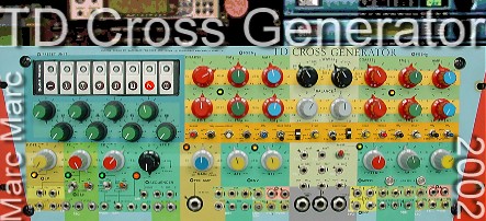
ManualTD Cross Generator
by Marc Marc (C)2002
|
0.01 |
This manual consists of several individual files, each containing one or more chapters. At your right hand you will find the table of contents. The red bullets indicate the start of a new file - the items underneath then are included to that file. |
0.02 |
Whenever you have questions about the explanation in this manual you should refer to the paragraph number which is listed at the left side column. This paragraph, which you are reading now for example, is numbered as paragraph 0.02 |
0.03 |
This manual uses a style sheet - please make sure that both style sheet and Java option are set enable for your browser. For response see Please describe clearly your question and at which page you came up with your question.
|
0.10 |
To this manualThis manual will explain all about the TD Cross Generator musical device - designed in 2002 . The "TD" is an enhanced reincarnation of the FF Cross Generator which was designed in 1984. Not only the technical features and possibilities will be treated but also the musical, spiritual and creative impact will come to an insight on a abstract level. With abstract level is meant that the style of the music one may prefer is of no concern for the abstracts, since this can be seen as a practical matter 'only'.
|
0.2 |
IntroductionTD Cross Generator |
|
|
Introduction
The TD Cross Generator (called "TD" from now on) is a modular analogueue device based on classical synthesizer techniques and featuring 'rare' options which intend to stimulate the joy for exploring experimental concepts in electronically generated music. |
0.22 |
Pandora's box
The design of the TD is a result of years of experience in experimental procedures (patches) with both traditional synthesizer based music and creative research on special procedures - only to be achieved by having the modular features as designed for the TD. The TD can be called a Pandora's box. It offers so many possible patches that it becomes, besides the standards patches, a device full with surprises. |
0.24 |
Specialty
The TD covers many possible procedures to generate both classical synthesizer sounds and interfacing with other instruments (electronic or acoustic by pickup). The specialty of the TD is taking use of the principal of "Cross Generating", a conceptual invention of Marc Marc done in the early eighties and explored over 10 years - producing a large series of exclusive tapes named "UNICUM" - released first at the Steel Plate label in '83. |
0.26 |
Explore your creativity
The TD offers for each musician a range of possibilities to express and explore the desire of creating one's own territory of sounds in a very creative and original way. Suggestions in this manual will be given in how to start to explore the TD - no matter what musical style you are aiming at. As a musician you have to experiment with these suggestions to find your way among all the features which the TD offers you and how to start thinking creatively with using the TD as part of a total setup with other musical devices, effects - both analogue or digital - MIDI based devices with MIDI/CV capabilities and analogue synthesizers. |
0.3 |
Cross GeneratingTD Cross Generator |
|
|
Introduction
Let's draw back to the concept of generating a sound by using the concept of 'cross generating'. To 'cross generate' a sound you need at least two frequency (tone) generators. The TD of course has these two generators.  Both generators are set to generate a certain frequency. Each generator is fed to the BALANCE controllers and the balanced output from the first generator is fed to the FM input of the second generator and vice versa.
Each fGEN also has a AM and a SYNC input and they also can be put in a CROSS modus - either by setting the input selection switches to create such an internal patch (SYNC) or by using the patch cables to inter connect certain outputs to the control inputs (AM). The idea of having one generator SYNC the other in terms of existing analogue synthesizer techniques - was very well explored by "Sequential Circuits" synthesizer design - the only analogue synthesizer designs wherein I could recognize these ideas - this leads to a complicated so called Sync Path: one generator controls the other in various identifying ways to control the colour of the sound. It is very hard to describe this colouring sound technique --> you need to hear it to understand. What can be said about is that the colour (timbre) of the sound can change rigorously and the system acts practically as an extreme filter - following the scale of notes because both generators are controlled by the same coarse voltage control to initiate their base tone. |
3.32 |
Speciality
In sense of the concept of Cross Generating Music the two generators control each other rather than sync to each other like in a Master-Slave principal. To prevent that both generators do lock into each others frequency and thus do sound like a single generator because they keep each other tight - features were designed into the TD to prevent his locking effect.
|
0.35 |
Read & Play
Just read this manual with the fun of reading about somebody with extraordinary ideas who likes to share this experiences to stimulate the ideal of playing as being a young one, just having a new toy. Skip whatever part of this manual you do not consider to be of your understanding - either by not wanting to understand or by being to early for this information. |
0.37 |
On the fly
While writing this manual I keep in mind that you might not know certain ins en outs which are a need to understand my explanation on certain features but, at the same time it is hard for me to keep track on this consistently over the whole manual because this manual is written on the fly to provide a customer with information and therefore has a improvised character. There is no doubt that I will forget to mention about certain possibilities. This, you should consider an advantage rather than a disadvantage because it gives you the necessary space to fill in yourself. There are many issues in this manual which I describe as being standard for my way of working with a modular application such as the TD and are partly based on general standards - those which you should be aware of and learn. At the same time there is plenty of space given to you by my suggestions to allow your own adoption of this knowledge and find out your very own way of dealing with an application such as the TD. I want you to have fun with it without being a copyist and therefore you will find this manual on your path not as being standard. |
0.38 |
Open Device
Another reason that this manual impossibly can cover all the possibilities of the TD is that the character of the TD acts like a "box of Pandora". It offers you to explore new ideas, you never came up with before - even when you operate with it already for many years. The TD is an 'open device' - always can be extended with new to add electronics/features or interfacing and most of all: new thoughts to explore. |
0.39 |
Alchemy of the heart
Each feature which the TD counts is an abstraction in treating and/or generating so called Voltages. These abstracts are the tools to create music - to turn the abstraction into something real which we know as being music in its most widest sense - to turn the abstract thought (or call it a feeling,- an intuition) into an output with the potential to touch ones feelings in a way that is typical for our time - a time wherein technology not yet did found its place. Turn anything into gold - the alchemy of the heart is the beat which dominates the development of technology. Musicians are the ones at focus to give shape to the unknown of the future and at the same time establish the past. Although the two so called fGenerators are forming the heart of the TD Cross Generator they are treated in this manual at last. This is because the complex of possible patches can be at best understood when first all other units are clear to you in their possible use. |
1.0 |
SequencerTD Cross Generator |
|
|
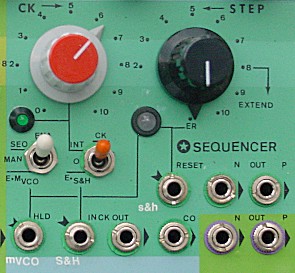
Introduction
The TD has an Eight step analogue Sequencer which is joined together with an eight step touch sensitive preset selection unit (TPU). Actually the Sequencer is a 10-step unit but it counts eight separated step controls to preset a voltage to control any Voltage Controlled parameter of the TD or any external device. The Sequencer has an analogue voltage output (P = positive) and a so called quantified output (N = normalized) via the internal link of Quantizer 1. This quantified output delivers a voltage which is tuned for V/OCT use to always have a tuned melody in case of use with proper V/OCT VCO's. The TD Sequencer has several logic controls to serve flexibility in using the Sequencer practically. Not only the Sequencer features a turn-switch to set the amount of steps involved in a single sequence cycle but also to externally control the RESET and HOLD functions.
In this simplified block diagram short cuts are used to indicated the functions.
|
1.15 |
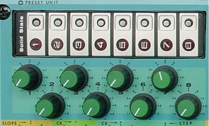
Touch Preset Unit
The Touch Preset Unit functions both as a display (LED's) to follow the Sequencer position and as a touchable unit to manually set one out of the eight positions (voltages) active (to the Sequencer output). First lets view the possibilities of this unit as a preset unit (without the Sequencer running). To use the Sequencer only as a manual preset control unit you have to set the switch "EN" (Sequencer ENable) into its middle position ("MAN" --> Manually). With the eight turn-pots (controllers) you can define an output going Voltage between zero and five Volts. These 'pots' are numbered 1...8 and correspond with the touch preset unit numbers 1...8. Thus touching the touch element number 1 will set the preset unit to its first position and thus will generate the preset voltage of the pot (control) number 1 at the output of the Sequencer unit. The Touch Preset Unit can act as a primitive keyboard to play 'Voltages'. Whether this means playing notes or other parameters depends on how the Sequencer output is used to control other units. |
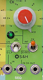
1.20 |
Sequencer Function
When the "EN" switch is put in the "SEQ" position (up) then the Sequencer becomes active. The Sequencer Clock (CK) generator produces a timing signal to have the Sequencer run at a certain beat. The controller pot to adjust this beat frequency is called "CK". A green pulsing LED indicates the beat (the rate that the Sequencer changes from step to step). When you use the Sequencer function you still can use the Touch Preset Unit. If you - for example - run a slow sequence you can fill-in a step by touching the corresponding touch element. This is useful for slow patterns. Have a base melody and make fill-in variations manually by playing the Touch Preset Unit. |
1.25 |
Sequencer outputs
The Sequencer has two outputs: the "P" output delivers a positive voltage relative to the position of the controls and the "N" output delivers a 'normalized' output voltage through the Quantizer unit. Practically this means that, when the Sequencer (or in use as a preset unit) is connected to control a Voltage controlled Frequency input of a VCO (Voltage Controlled Generator), the "P" output will let the tone become higher when the pot is turned to its right. But the height of this tone can be set at any frequency within the Voltage range which you can set with the control pots (analogue control).
|
1.27 |
Practically
The Quantizer is internally patched to a LOG converter to provide fGenerator 2 with a voltage which is necessary to create a V/OCT function. Secondly the LOG output is connected to an INVerter to turn a positive voltage into a negative one. Now, lets view the possibility of having both fGenerators (VCO's) generate a melody but in an opposite way. One is controlled by the "N" output (Normalized/Quantified) of the Sequencer which runs through the LOG converter and will produce a up going melody. The other one is controlled by the same control voltage but inverted through an INVerter and will produce a down going melody as being a mirror of the other fGenerator. Of course both generators can be set to a certain center frequency with their COARSE and FINE frequency control. The Sequencer is set to voltages that generate with the VCO's a pentatonic note pattern because it is the most easy way to demonstrate the effect of using these two control voltages. As you know a pentatonic based tone scale easily combines notes.
Of course, you can start with more complex patterns/harmonies and find - by playing with the controls - how tones fit together in a way you maybe never could predict and creating a sequence of tones (a melody) which is surprising for you and useful for a new piece (song?). When you continue to read this manual you will find out that the principal of mirrored output voltages may deliver you quite some ideas for generating 'rare' effects. |
1.29 |
The Moral
Changing Phase (polarity - positive/negative) in a 'complex' setup of controls is worth playing with. The TD is equipped with two independent inverter-units to change polarity of the applied signal --> positive becomes negative and vice versa. |
1.30 |
STEP Switch
With the turn-switch "STEP" you can set the Sequencer to run 2...8 steps in a cycle. And you may set the switch to a position to extend step 8 one or two Clock (CK) cycles (9,10 step position). You may set it to an external reset control (interrupt the cycle before it has reached step 9 and reset it to start at step 1 again). Changing the position of the "STEP" switch means shortening or extending the Sequencer cycle. Once you - for example - have set a melody of 8 tones - you can try to set the Sequencer to a different amount of steps to wipe out tones and listen what the result is. OR, you might want to build up a sequence. First start with 2 or 3 notes until they fit and then turn the switch to generate 4 notes and play with the control number 4 to add a note to your sequence. Continue to the next note and so on until you have reached the note eight and then see what happens is you extend the time duration of this eight note with 1 or 2 clock cycles. |
1.32 |
Practically
|
1.35 |
Carry Out (CO)
The "CO" output of the Sequencer carries a signal out that represents the start of a cycle of the Sequencer. The Sequencer rotates from 2 to 8 steps (extended to 10 steps possible). At each start of a cycle - during the first step the "CO" turns to a high logic level. |
1.36 |
Practically
This "CO" output level could be used as a trigger (at its up-going edge) to start (to trigger) another event which will last the whole Sequencer cycle or a part of it until the next cycle starts and the event which will be triggered by the "CO" logic level again and cause a change for this next cycle. The "CO" logic level is typically meant to be functioning to synchronize parallel processing over each cycle of the Sequencer. |
1.37 |
Example
The "CO" output could be used to trigger the Sample & Hold (S&H) unit. The S&H unit is set to generate a random voltage constantly each time it is triggered. This random sampled voltage could be used to (for example) control a voltage controlled filter (VCF) to set its filter frequency to control the upper-tones level (timbre). Each time that the Sequencer completed a cycle and starts a new one, the S&H unit is triggered by the "CO" output of the Sequencer - which indicates a start of a new cycle - and chooses a new random voltages to be hold until the next start of cycle. Because in this example this S&H random voltages is applied to a VCF, this will result in a repetitive sequence of tones with - depending on the depth of the VCF modulation depth - a changing of the timbre of the sound at each Sequencer cycle. You also may modulate the amplitude by applying the S&H voltage to a VCA or AM input. Or, apply it to the FM input of o Modulating VCO (mVCO for example) which is used to create a slight change in vibrato effect on a main tone generator. With this principle you can modulate a simple melody (sequence) in such a way that it remains exciting - even when it is repeated infinitely. Instead of repeating a sequence all the time in a same manner, you can play with repeating it with having more or less changes. What you chose to change at each cycle is fully up to your fantasy and possibilities of your devices. |
1.38 |
Some other suggestions
- Triggering an Envelope Generator (ADRS or AR - Attack, Decay, Sustain, Release) and use the envelope output to modulate a VCF. - or a VCA (Voltage Controlled Amplifier). Then the Volume could be starting attenuated at the start of the sequence and then drops down slowly. When you would route the sequence sound to a reverb unit and send the reverb output to a VCA which is controlled by an envelope which is triggered by the CO output and mix this reverb output with the dry sound, then the sound can start with a reverb character and during the sequence turns dry (depending on the ADSR) settings. Thus, you also could let the start of the sequence begin dry and slowly having the reverb turned open by the envelope signal - applied to the VCA.
|
1.39 |
The moral
Changing sounds during a sequence makes the repetitive sounds more alive but at best when there is a sort of synchronization in the beat. |
1.40 |
Reset (ER)
The STEP switch also has a position which is called "ER". This means External Reset. When you put the STEP switch into the ER position it runs at a sequence of 8 steps but an external RESET pulse, applied to the RESET input, may reset the Sequencer to step NR 1 and thus modifies the amount of steps that the Sequencer will run during a cycle. Each time that the external RESET input sees a positive going pulse, it will reset the Sequencer to step NR 1 at the moment that the CK (Clock) pulse of the Sequencer will arrive. This means that an incoming reset pulse (logic level at its up going edge) is memorized and only will be executed at the next following uprising edge of the Sequencer Clock (CK) pulse. In more musical terms this is called beat-synchronizing. When a reset pulse comes in, then the big LED will turn Green or Yellow to indicate that a reset is about to come at the next Sequencer CK pulse. As soon as the Sequencer CK pulse is executed the LED will turn off again (or becomes red - due to an active HOLD input). The illustration below shows you the fundamental principals of the RESET and HOLD function in relation to the Clock beat.
Notice the Green areas. They indicate the time between an incoming reset level and the actual moment of the reset event (green goes off).
|
1.42 |
Practically
The possibility to reset the sequence in a synchronized manner is very valuable to create pseudo random Sequencer patterns. The Sequencer only counts 8 steps but with the reset interrupt it can act as a Sequencer with virtually hundreds of steps. Set the STEP switch into it ER position and use the S&H CK control to determine the reset rate. Set the S&H CK rate always lower than the SEQ rate. For example at approx.. 1/2 or 1/3 speed and at best not exactly. The Sequencer will for example reset at first at the 4th step but the next time at the 3rd of the 5th and maybe another time at the 2nd or remains one CK cycle at the 1st step. When the sequence control pots are set to a proper scheme of tones this will generate a random melody which might sound as if it was composed.
|
1.43 |
Remote switch
You can apply a remote push switch to the reset input which shortcuts the input signal momentarily to ground. When the switch is pushed in, a reset pulse is generated. When the switch is pushed in an then released, you might generate a reset pulse too but this is due to the so called bouncing effect of the switch. So the best is to shortly push the switch. What also can be interesting to use as a command switch, to reset the Sequencer manually, is a so called 'old' slide projector remote switch. This is a push switch build with a handy shaped grip. The switch usually just shortcuts the two poles of the input it is attached to. When the plug of the switch is not the same as necessary for the TD, you simply can change it. With such a handy slide projector remote control you could easily rhythmically interfere with the running sequence. |
1.45 |
Hold (HLD)
The HLD input of the Sequencer can have the Sequencer be stopped based on the logic level applied. When the HLD input is low (zero) then the Sequencer runs. When the input is High (+5 Volt) then the Sequencer stops running until the input becomes low again. To make the HLD input active you must set the EN switch in the HLD position. The big LED turns red when the Sequencer is in HOLD level but whether the Sequencer also will turn into the hold state depends on the position of the EN switch. Only when this switch is set into the HLD position the hold function is effective. The HLD input is internally connected to the SQR (Square) output of the mVCO and thus; when you switch to HLD position the rate of the mVCO will control the hold function. You also may apply any external signal to the HLD input - even when is not a logic signal. The hold state will be seen at the HLD input when a voltage of 2.5 volts is seen. |
1.46 |
Remote switch
You can apply a foot switch to the HLD input which shortcuts the input signal to ground. Just plug in any foot switch and try. When the switch is pushed in, the Sequencer runs and vice versa. The foot switch maybe of a type that need to be held pushed in but also a type that changes the state each time you push it (as with the 'old' guitar effect boxes usually). This is up to what you prefer. The same as what was mentioned for the reset function in context to a slide projector remote switch can be said for the hold function. |
1.47 |
Synchronization
The same as with the reset input the hold input is synchronized with the SEQ CK pulse. This implies that when the hold level at the input turns from high to low (from hold to run / stop to start) comes in, the Sequencer waits for the next CK pulse to run again. But in contrast with the reset sync the hold function (the stop function) becomes active immediately. Thus, to stop the Sequencer and holds its current position is not waited until the next CK pulse. To have the hold function wait until the next CK pulse before having the Sequencer continue running is important to be able to perfectly synchronize on the beat. The illustration below shows you the fundamental principals of the RESET and HOLD function in relation to the Clock beat.
Notice the RED areas in the illustration. They represent the big LED to lit red. Also notice the YELLOW area. This represents the LED to lit yellow due to the fact that both an incoming RESET and an incoming HOLD level is detected. You also can see that a RESET event can take place when the Sequencer is in the HOLD mode (overrules the HOLD mode).
|
1.48 |
Practically
Besides using the hold function to control the Sequencer run with a foot switch - which is very practical - you also can use the hold function to create pseudo random patterns. Internally the HLD input is connected to the SQR output of the mVCO. Set a low frequency of example 1 Hz (1 second) and run the Sequencer at 8 BPS. When the Wave Form control of the mVCO is set at its center position the SQR output will have a duty cycle of 50%. This means that for each period of the SQR wave form the level will be 50% of the time duration high and the other 50% low. In this example this means 0.5 seconds high and then 0.5 seconds low. Thus, the Sequencer will repetitively in hold state for 0.5 a second and then run for 0.5 seconds. When it runs with a rate of 8 BPS it can run through 4 steps when the Sequencer, if not in hold position, and then hold the 5th step for 4 BPS before doing the next 4 steps and so on. When you have set the STEP amount to 8, then this leads to a repetitive pattern of 12,3,4, hold, 5,6,7,8, hold,1,2,3,4, hold etc.. But, when you have set the step amount to for example 7, then your pattern will be as follows: 1,2,3,4,hold,5,6,7,1,hold,2,3,4,5,hold,6,7,1,2,hold,3,4,5,6, and so on. As you can see this creates an interesting pattern. By differing the step amount and the frequencies of the CK and mVCO, you can explore all kind of possibilities to pseudo randomize your sequence. When you change the Duty Cycle of the SQR form 50/50 to another ratio - by turning the Wave Form pot - you change the ratio of the hold and run time of the Sequencer. This generates again different patterns. And, when you also start to have the reset function involved by control of an external generator the horizon of the field you are facing cannot be seen - you have to walk towards it and every time a new horizon shows up. Very important is the fact that both the reset and the hold function synchronize at the beat of the Sequencer Clock pulse. |
1.50 |
Sequencer Clock (CK)
With the Sequencer CK control you can set a frequency from 0.2 Hz (each 5 seconds a pulse - a beat) to 100 Hz (100 pulses - beats per second). A 'normal' sequence, when it concerns the creation of a melody sequence, is set between 4 to 8 beats per second. But, because the Sequencer output can be used for many purposes, other rates become effective too. Of course the slow range is of value for slow sequences - in particular for background or secondary melodies. The fast range can be interesting to create distort sounds or in combinations with other units to create random patterns (voltages / wave forms) to control a VCF for example.
|
1.60 |
Clock (CK) Select
With the CK select switch you can select which CK signal will be used to drive the Sequencer:
The external CK input is internally linked to the S&H CK output. So, it is easy to synchronize the Sequencer with the S&H speed by simply having both triggered by the same CK generator. In this case both by the S&H clock generator. |
 First, study this simplified block diagram to get familiar with all the functions which the Sequencer unit features. Next, in this chapter all functions of the Sequencer will be discussed.
2.0 |
Sample & HoldTD Cross Generator |
2.01 |
Introduction
The Sample & Hold unit - simply named S&H - samples an input voltage sequentially at command of a Clock (CK) pulse and then holds this sample (momentary level of the input voltage) until the next sample command (ClocK pulse). When applying a varying voltage at the input - for example a random voltage which is contiguously randomly varying - the output of a S&H unit is a sequence of random voltage jumps at the beat of the CK rate. You could say that it is a Sequencer without controls to set the voltage for each step (an infinite random sequence). The S&H has an analogue voltage output (P = positive) and a so called quantified output (N = normalized) via the internal link of Quantizer 2. This quantified output delivers a voltage which is tuned for V/OCT use to always have a tuned melody in case of use with proper V/OCT VCO's. A S&H unit can be used for many purposes. The most common practical features and the possibilities of the S&H unit which is implemented into the TD will be covered in the next section.
|
2.02 |
Practically
The most common purpose of a S&H unit is to generate a random or pseudo random pattern which usually is used to generate a melody or to modulate a filter (VCF). When it is used for melodies it result in a random melody or pseudo random melody - depending on the input signal. When is used to control a filter (either the frequency or the resonance), the timbre is randomly changed. A mouth Harp for example can be very well imitated when holding a tone stable and only varying the filter frequency by using a random S&H pattern. The S&H output can be used to control any voltage controlled parameter. It is a matter of your own fantasy for what purpose you like to use it.
You also can plug in (patch) to the external inputs (indicated as RED). |
2.10 |
S&H CK rate
With the CK control pot you can set the CK speed at to 0.1 Hz (1 beat per 10 seconds) to 80 Hz (80 BPS). The rate is indicated by a green LED which shortly flashes at each CK pulse (beat). |
2.20 |
S&H CK Select
With the CK select switch you can select which CK signal will be used to drive the S&H:
The external CK input is internally linked to the SEQ CK output. So, it is easy to synchronize the Sequencer with the SEQ speed by simply having both triggered by the same CK generator. In this case both by the SEQ clock generator. As you noticed the SEQ and S&H CK are cross-linked by both the CK select switches thus when you like both the SEQ and the S&H by synchronized you have the possibility to preset two different rates and use the switches to toggle between them. Also, when you synchronize the units and choose the SEQ CK generator to drive them both, you have the S&H CK generator available to use in junction with the HLD and/or the reset function of the Sequencer or for other purposes. |
2.25 |
External Clocking
You can patch the external CK input to any signal, either logic or analogue. Normally you will patch it to a logic signal. Preferable levels are: Low = ground and High = +5V but, the input is protected against negative voltages and voltages which exceed the +5V. Thus also the +10V trigger and gate signals from other analogue synthesizers can be applied. The CK input is based on an internal TRIGGER. This means that at the moment an input CK signal reached +2.8 V, a Sample is taken for a very short moment. To be able to sample next, the CK input level first need to drop below +1.8 V. This will be sufficient for almost any signal available on the TD and external devices. When you apply an analogue signal to the CK input it is internal translated to digital levels. Thus, it is possible to apply analogue signals to the CK input. |
2.27 |
Examples of external Clocking
- When you are using a keyboard with GATE and TRIGGER outputs you can use them to Clock the S&H. Using the TRIGGER signal means that each note you play will cause the S&H unit to sample new. When using the GATE signal means that only a sample is taken when you play staccato. - When you are using a MIDI based, either with a computer or musical instruments: When you are using a computer program to compose, you can edit a time line which triggers the S&H unit. Of course you do need a proper MIDI interface which can translate the program code for this time line to a pulse to trigger the S&H CK input. - When using MIDI keyboards and/or expanders, you have to see which gating or triggering outputs they are equipped with or how to make them available by using a special MIDI interface/translator. Interfacing to a computer program or other devices is useful to synchronize the S&H event(s) with the total musical line.
|
2.30 |
S&H signal input
The S&H signal input (the signal to sample) is internally connected to the LP (LOW PASS) unit output which on its turn is connected to the noise generator. These internal links make that normally the S&H signal input is driven by a random voltage and the speed of this random can be controlled with the SLOPE control pot. The result is that the S&H output delivers a complete random voltage sequence at the rhythm of the CK signal. |
2.35 |
S&H signal input select
With this switch you can select:
|
2.40 |
S&H outputs
The 'P' output delivers an analogue positive voltage. The 'N' output is the 'normalized' output from Quantizer 2 which is internally linked to the S&H 'P' output. Hints for using the outputs: Using the 'P' or 'N' in combination with an INVERTER to control two generators independently results in a tone sequence of two tones which mirror their distance relative to the center tone position.
|
2.42 |
Generating pseudo patterns
Depending on the settings you also can have the situation that a pseudo pattern has a short cycle and thus is not so pseudo but this provide an exact tuning of the several parameters involved. And again a slight difference in CK speed for example may just be enough to jump to another pattern.
In the graphic you can see a RED indicated sample level. This level may be due to sample exactly at the moment the input Square wave from the mVCO is rising. The rising time of a Square wave takes time - although this goes very fast. In the TD it might go too fast and this 'in between' rare occasion - which may be very interesting - may not occur so easily. But, you can simulate it and even determine how many times it might/will occur. How?
|
2.44 |
Advise
Therefore it is extremely important that, when you have found a good sound (riddle / pattern sequence etc..) and you are in a recording state that you also record it because you never may get it back. It happened many times in the beginning of my playing with my own made devices that I did regret that I did not record a track to be used later. I even did regret that when I started to record more often things that I found too shortly. I recorded certain nice sound sequences for example for a minute or 5, having all kind of subtle nuances on a random or pseudo random base and found out later that it could be a nice piece of 'minimal' music as it was when it lasted 30 minutes. Simply copying is to have it turned into 30 minutes does not work because with pieces like this it goes about the slow mutation or the all of a sudden unexpected but fruitful jump in melody or timbre or rhythm. |
2.50 |
Patch Idea 1
In this Patch example, I will explain you a feedback-loop which I myself never tried but appeared into my mind on the fly when writing this manual. I could verify this patch with the TD - while it is still on my table - but, on purpose I will not. Instead I will describe this patch idea from a distance - as being an abstract idea which give you room to adjust it yourself when trying and experimenting with it to implement, knowing that it probably is not done before. Marked with RED are differences in the 'normal' internal patch of the units. The broken lines show you 2 possible patch lines (you take either one of them). The basic idea
The speciality - the feedback of the patch - lays in the fact that either the quantified or the LOG output of the S&H unit is fed back to the FM input of the mVCO to Frequency Modulate its Triangle output frequency. Realize that the mVCO is the source input of the S&H unit and thus by feeding the output of the S&H back to this mVCO to control its frequency. The following abstraction is true:
And, do not forget that you may patch any unit in between the feedback path to alter the feedback signal. For example patching the ENV unit in between to achieve a delaying effect. And more.... whatever you're fantasy is triggering you simply should try out to find out that results are not always due to rational thinking. |
 Take a view at this graphic as a representation of generating a random pattern (melody if you wish). The input signal is a Random voltage which is delivered by the Noise unit through the LP filter. The output is a random sequence.
 This simplified diagram shows you how the S&H unit is build up.
 This diagram shows you the complete setup for a S&H module as it is incorporated into the design of the TD. As you can see there are 3 units attached - each also to be used on its own.
 When the S&H signal input is applied to a triangular wave form (from the mVCO for example) the S&H output is not random anymore as when applying the random signal form the LP unit. Instead it become pseudo random. The reason is that the triangular wave form is a stable and strictly defined dynamic voltage - swinging up and down according a periodically timing. The S&H CK also is stable and thus two strictly defined timing are running asynchronously. In theory there always is a starting point which can be taken as a reference point in the combination of CK timing and mVCO wave form progression. This point will come back over time but how long this will take (how many notes will be played before the whole sequence will repeat) depends on the settings of the controls. And because the TD is an analogue build up device, the time to have the pseudo cycle repeat itself may have caused a change in environmental temperature or moisture which, although slightly, change the electronic response. Thus, maybe the pattern never will repeat.
 A simple way to create a pseudo pattern of only two notes is to feed the S&H signal input with a Square wave form (TTL output) from the mVCO. Set the CK rate at your desired pattern rate and then play with the frequency (rate) of the mVCO. The TTL Square of the mVCO only knows two conditions: zero and +5 Volts and thus the S&H output only will reproduce these two conditions. But, due to the asynchrony of the S&H CK rate which commands the takeover (sample) of the momentary input level (the TTL Square wave of the mVCO) you will get a pseudo pattern of the two levels (two tones/notes if used to control the frequency of a VCO/fGenerator). Although simple, you will be surprised how interesting this can be when you start playing with both the CK rate and the mVCO frequency. It can result in a non-useful pattern but also in a very swinging pseudo pattern that sometimes - all of a sudden - may change its character or randomly puts a note in between due to the coincidence of taken a sample exactly at a the rise or fall moment of the Square input signal.
 View the following setup (patch) and notice that the rise and fall times of a mVCO Square wave form is SLEWED by the LP unit. with the SLOPE control set to minimum you already achieve a slowing down of the rise and fall time of the SQR wave from the mVCO unit. Turning the SLOPE control more to the right will increase the rise and fall time and thus will change the character of the 'simple' pseudo pattern and increases the chance to get a 'in between' voltage/tone.