3.0 |
Noise GeneratorTD Cross Generator |
3.01 |
Introduction
The Noise generator has the function to produce a so called White Noise (WN) that is as white (flat) as possible. The Noise generator of the TD delivers at its WN output such a noise. It is in contrast to many regular musical instruments analogue generated noise. The White Noise quality of the TD is better than most classical and modern digital noise generators because the selection of the transistor which is responsible for generating the noise is selected from many of hundreds of transistors. This is not done only for the TD because that would be a little too much. It was done years ago once and all the candidate transistors were registered and stored. So you have a very nice flat spectrum analogue noise output on all noise generators units produced by Marc Marc. |
3.10 |
Noise level and blowing tweeters
The noise output level is high (10 volts swing) so be careful with applying it to normal Hi-fi equipment because it may blow (in particular) your tweeters when the volume is set to high. Always put your volume down at first. |
3.20 |
coloured Noise
The Noise signal is meant to deviate a so called coloured Noise (CN) from. This is a coloured noise that is weighted differently in frequency spectrum. It sounds for the ear more low. |
3.30 |
Random Voltage
The CN noise signal on its turn is the base to generate a so called random voltage. This is done by applying the CN output to the LP unit input and delay the signal with the SLOPE control.
|
3.40 |
Using the WN and CN noise outputs
You can use both WN and CN noise signals as a base to create a final sound. You can apply it to a VCA and or VCF and use a ADSR unit to determine the envelope --> use it as a Synthi-drum audio signal. You can apply it to any filter and manually imitate various noise based sounds such as rain, wind and storm. With digital noise you can do all of this too but the result of digital noise is a big laugh compared to a good analogue noise signal as from the TD.
|
|
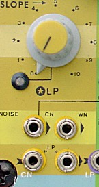
 This schematic shows you how the NOISE and LP unit are symbolized and tied internally together.
4.0 |
Slope / Low PassTD Cross Generator |
4.01 |
Introduction
The LP unit with its SLOPE control is basically a Low Pass Filter. But, it is not meant to be a filter for audio signals, although possible. Instead it functions as a rigorous delay for control signals. With the SLOPE control you can set the A and R time (Attack & Release). Another way of putting it is that you are controlling the so called SLEW RATE of the rising and falling envelope of a voltage. The input of the LP unit is connected with the CN output of the noise generator (coloured Noise). With the SLOPE control you can turn from a rapid random voltage (coloured Noise) towards a slower random voltage with frequencies that go below audio.
When applying audio signals (such as coloured Noise) the LP unit acts like a Low Pass filter doing, seen from a fundamental point of view exactly the same). |
4.10 |
Rain and Storm
Although the LP unit is not in particular meant for audio, it still has a nice feature to create storm and thunder sounds. In the most left position of the control the coloured Noise is almost unharmed and sounds like a rainy noise. When you turn the SLOPE control to its right slowly, you then will create a more heavy rain sound as with thunder and stormy weather far away. |
4.20 |
Random
As already said, the LP unit most of all has the function to create a random signal. Turning the control a little more to the right will lead to a random voltage which, when used as a control voltage for FM or AM clearly will modulate a parameter (frequency or amplitude) in a random way. The more you turn the SLOPE control to the right the more slower the variations are. The disadvantage of the SLOPE control is that the more slower the signal also the more little the amplitude of the LP output signal is but, with this you have to live. Still, the SLOPE control - even with this handicap, gives you a range of possibilities to generate effect, distort sounds and audio based noise effects. |
4.30 |
Hint
Plug in the WN and or CN, LP output into any Voltage Controlled input you have of any device and play with the control depth to see how the response is. You might find out some interesting sounds. |
4.40 |
Suggestions
What is the use?
When the sweep of the mVCO on its turn would be determined by the ENV follower - driven by a Synthi-drum pickup - this would create a more interesting sound curve than with a constant modulation depth When instead of a SQR and TRI (triangular) wave form is used then, the wave form at low frequencies is the same as with higher frequencies but still the amplitude decreases proportionally with the frequency. |
|
 For clarity the illustration shows you how the LP unit responds on a Square wave. You can see that the LP unit can SLOW (SLEW) down the response time with the SLOPE control. It delays the voltage rise or fall (the attack or release).
5.0 |
Pre AmpTD Cross Generator |
5.01 |
Introduction
The TD operates with high level signals. To connect external signals with a low amplitude to the TD is possible but may not give the result you like to achieve. You then need to boost up your signal with the Pre-Amp. The Pre-Amp unit is an amplifier which can amplify both AC (audio) and DC (voltage levels and slow changing voltage) signals.
|
5.10 |
Gain
With the GAIN control you can set the amplification from 2 times up to 2400 times. This range is enough to amplify any signal applied. For the use of a Microphone you need to almost turn the GAIN control open to amplify the signal at an appropriate level. Some gain setting indications for several possible to connect devices:
|
5.20 |
Distortion
When you amplify a signal 'too much' the output of the Pre-Amp will distort the signal. Because there is so much gain overhead, you can use the Pre-Amp with the gain fully open as a (for example) guitar hard-distortioner and use it either for audio as is or as a control signal. When you apply a control signal generated within the TD setup and set the GAIN fully to the left, then you will amplify the control signal with 2 times and thus will cut off the top (plus) and the bottom (minus) range of the signal because the Pre-amp cannot reach a level twice as high as the maximum and minimum voltage levels from control signals. This can be useful to cut of the tops of a Triangular, Ramp, Saw tooth or Sinusoidal wave form more or less - depending on how much 'over-gain' is set with the gain control. When using the distort output to modulate AM and/or FM you easily can hear the effect of it. |
5.30 |
Input
The Pre-Amp input is a large Jack input for convenience - to have a strong and tight contact. When you connect a commercial Microphone you can plug in straight away. When using a professional one with an XLR plug you can use a conversion plug.
|
5.40 |
Pickup elements.
The Pre-Amp first of all was designed to amplify pickup elements to be used for a Synthi-drum setup of the TD and to pick up whatever signal to be used to modulate AM and/or FM the generators to create more or less weird effects. More about this in the chapter 6.0/ ENV. |
5.50 |
Ring Modulated Voice
The Pre-Amp also is useful to directly interface a MIC to the AM input(s) of the fGenerators to create the so Ring modulator effects with your voice. Later in the manual this will be discussed. |
5.60 |
Indication Led
An orange coloured LED indicates the level of the amplified signal.
|
|
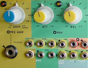
 This diagram shows you how the PRE-AMP and its internal connection to the ENV (Envelope Follower) is symbolized.
6.0 |
ENVTD Cross Generator |
6.01 |
Introduction
ENV stands for ENVelope follower. An Envelope Follower is basically an AC to DC converter. It generates a DC levels that corresponds to the average peak level amplitude of an AC input signal. It follows the average amplitude (volume) by a corresponding voltage level. This voltage level can serve as a control voltage for other modules. For the TD is chosen for not only an Envelope follower only. Also a so called AR generator (Attack and Release generator) is incorporated. Practically this means that you can control the way (the character) of following the input signal by a representing control voltage with both the ATT (attack) and the REL (Release) control. Between fast following (ATT and REL minimal) or follow slow following and even in function of a so called PEAK detector/follower.
The ENV in combination with the Pre-Amp can function as a pickup element for a Synthi-drum setup. |
6.10 |
Synthi-drum
The output of the Pre-Amp is internally connected to the input of the ENV unit. When you attach a microphone to the Pre-Amp and set the gain control to have it amplify the MIC signal about 1000 times (gain is set at '8'), you then can use the MIC as a 'beat-element'. The ENV will deliver a control signal with the envelope of the MIC signal. When you keep the Attack control fully to its left and start to turn the Release control a certain amount to the right you then will extend the fall off curve of a beat on the Microphone. Typically a curve that is used for a Synthi-drum. Also setting a certain amount of Attack will let the envelope curve more slowly rise and this results that a single beat let the ENV signal only rise a little before its falls off again and a series of rapid beats will let the ENV curve rise in phases. You also can set a Attack time and keep the Release time at zero. A series of beats will let the ENV signal rise in fazes and after the last beat drop immediately to zero. |
6.13 |
Synthi-drum pick-up elements
As was said, a microphone already can function as a pickup to be used in a Synthi-drum setup but, a more suitable (playful) pickup element would be a small metal or wooden box with a dynamic or piezoelectric element mounted inside that box. You can beat with your thumb, more fingers or a drumstick at it to generate envelopes to be used with the fGenerators to create a Synthi-drum. |
6.16 |
Synthi-drum example
Apply the ENV signal to the AM input of a fGenerator (internally linked to the AM input of fGenerator 1 - AM switch to ENV position - and internally linked via the INV unit 1 to the AM select switch of fGenerator 2). Set a frequency with the fGenerators and adjust the AMP controls to have the fGenerators not produce a tone. When you beat t your box the generated envelope will let the tones come up proportionally with the envelope curve. The 2nd fGen is Am controlled with the reverse voltage of the envelope output signal but in this case this would not matter but when you set AMP control of the 2nd fGen to have sound when no envelope curve is present then, this fGen will act in the opposite way: a sound will be preset until an envelope (a beat at the box) will occur. Thus, the 1st fGen will start to produce a tone while with the other fGen the tone will disappear. Until the envelope fall off and the tone of the 1st fGen will disappear and of the 2nd fGen will rise up again. So, by beating the box you mix form one to another tone. Of course you can modulate the fGenerators at the same time FM. Also using the envelope signal by patching them to the FM inputs. You could use the direct ENV output to patch into a FM input of the 2nd fGen and the INVerted envelope signal (from INV 1) to patch to the 1st fGenerator (thus swapping the inverted ENV signal for the FM use). Then also the frequencies will change and while the one will rise in tone the other goes down. Also applying noise or the random noise/voltage for the LP to the FM inputs can be very effective. It will 'noisify' the sound. Once you have learned all about the weird sounds you can create with modulating the fGenerators you will be able to also use these sounds in a Synthi-drum setup. |
6.20 |
Use as an Envelope Follower
|
6.25 |
Example
This illustration shows you a simplified diagram on how possible to use the ENV unit in a feedback Amplitude Modification loop (AM). Notice that you only need to make one single external patch connection because all other connections are already internally wired by plugging switch contacts at the inputs. Many details of the fGenerators are not shown in this illustration because they would lead us away from the basic setup. The Patch line indicated with RED can be tapped from any output of fGen 2. Either the balanced output which also connect to the Wave form selectors of both fGenerators or one of individual wave form outputs. By patching to one of the balanced outputs you may feedback from a mixture of both fGenerators or only one of them by setting the Balance control accordingly. The two fGenerators are standardly setup in a cross feedback loop when certain switch selections are made properly. This crossing feedback is indicated by the crossing FM lines. Not shown are the two internal Crossing SYNC lines which also can be involved.
The output amplitude of fGen 2 influences the output amplitude of fGen 1 by the AM input through the ENV unit. The output amplitude of fGen 2 is influenced by its own output amplitude feedback through the inverted ENV signal. When the output amplitude of fGen 2 raises, then the amplitude of fGen 1 goes down. At the same time the amplitude of fGen 2 goes down and thus will the amplitude of fGen 1 goes up again.
Also the FM and SYNC paths may feedback to makes thing more complicated. When no extra 'precautions' are taken this leads to the fGenerators locking on to each other with the result of an output signal of both generators with a so called superimposed frequency. This is a base frequency with another frequency imposed onto it. You know this effect basically as FM synthesis - made popular by Yamaha with their DX synthesizer series.
Now, let’s draw back to the use of the envelope signal in this setup. When the result of the cross feedback loop of the 2 fGenerators gives you an interesting sound at some point but you would like to break the lock between them or tighten it, you could use the envelope unit in a feedback AM control loop as just described.
When you try to achieve an interesting sound with this setup, do not be discouraged when not immediately having success. Build up the patch but keep, at first instance, the depth controls of the feedback back at zero. Then experiment by slowly turning one or the other control and see what happens. Try and learn and then try to combine. Also realize that the frequency range in this setup is important. Within audio frequency (creating a melody) the requirements of the control settings are different as when you use this setup to generate a low frequency pattern. You might very well use this setup to generate a pseudo random pattern of a wave form to be used for modulation purposes to other VCO's or VCF's or to feed the S&H unit to create pseudo melody patterns when used with an external VCO. |
