7.0 |
mVCOTD Cross Generator |
7.01 |
Introduction
The name "mVCO" you will not find in standard synthesizer module language. The most closest would be VC-LFO (Voltage Controlled Low Frequency Oscillator) but because the mVCO also can generate frequencies within the audio range. I decided to make up a new name that would distinguish it from other modules. VCMO sounds a little strange and thus it became mVCO. As the "M" indicates it is an oscillator for modulation purposes and not to generate audio frequencies to be heard as tones in a final musical output (although it is possible). The reason to also have the mVCO produce audio range frequencies lays in the concept that when the response time of AM and FM inputs is fast enough you can create much more effects. |
7.10 |
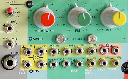
Wave Forms
The mVCO has two outputs. The SQR TTL output delivers a squared wave form at a so called TTL level (0 to +5V swing). This TTL level makes it easy to use the SQR also for 'clocking' digital inputs (such as the S&H and SEQ input controls and external logical controls such as Trigger, Gate and Sync controls). With the WF control pot (Wave Form Control) you can set the so called Duty Cycle of the SQR. The Duty Cycle is the ratio of the time that the SQR is at low and at high level within one period. You can vary the Duty Cycle from 1 to 99 % - from a short pulse up to a short pulse down. In the middle position of the WF control the Duty Cycle is 50/50. The TRI/SAW output delivers a Triangular, Saw Tooth or Ramp wave form - depending on the WF control pot (Wave Form control). In the most left position you will have a Ramp wave form (fast rising and slow falling), at the middle position a Triangle wave form (equally rising and falling) and in the most right position a Saw Tooth wave form (slow rising and fast falling). Thus you can set the wave form anywhere between these main shapes |
7.20 |
Frequency Control
With the FREQ control you can set the frequency. |
7.24 |
Frequency range
With the RANGE selection switch you can set the frequency range that the mVCO can swing from minimum to maximum control voltage.
|
7.24 |
FM (Frequency Modulation)
With the FM input and FM control you can modulate the frequency with an external voltage. This voltage can be any signal - either from the TD or an external source. Either (semi) static (keyboard), low frequency or audio frequency. |
7.30 |
Use
The use of the mVCO in combination with the other modules of the TD are many. By internal connections the outputs of the mVCO already are connected to inputs of the other modules.
The TRI/SAW output of the mVCO is internally connected to the AM function of both fGenerators (via the AM selection switch). This can produce Tremolo effects or, when the frequency of the mVCO is set to audio range, ring modulation like effects. The SQR of the mVCO also is internally connected to the HLD (hold) input of the Sequencer to function - when the Sequencer is set into HLD mode - as an automatic 'hold' generator (best at low frequencies) to generate pseudo random Sequencer patterns. |
7.33 |
Wave Form Control
Hence that the setting of the WF control is important to generate all kind of variations and effects for certain patches. Remember that the WF control both effect the TRI/SAW and the SQR outputs. |
|
8.0 |
INVertersTD Cross Generator |
8.01 |
Introduction
Two independent so called inverters are available.
INV 1 is internally connected to the ENV output and just produces a negative output. When the ENV is set to function as a Synthi-drum envelope signal generator then, the effect of the inverted signal may lead to an opposite function. For example a down going tone instead of a up going one. The output of the INV 1 is so to say a mirror of its input with a negative polarity. INV 2 is internally connected to the LOG 2 unit and thus produces a mirror with a negative polarity of the LOG 2 output voltage. Thus, the INV 2 output would let a tone go down instead of going up if used for FM control of the fGenerators. |
8.10 |
Use
You can use the INV units for any signal path to have it inverted. It can deal with both AC and DC signals (thus both audio and steady or low dynamically changing voltages). The only thing you cannot do is to invert a TTL level SQR and then use it as a logic control for the S&H or SEQ units. This is because these logic control are based on a positive SQR and the INV unit would turn it into a negative voltage based SQR --> thus no response. You very well could use the inverters to interface with other devices. Both to invert analogue control signals and to bring logic levels to its proper polarity level (invert plus and minus and vice versa). |
|
9.0 |
LOG convertersTD Cross Generator |
9.01 |
Introduction
The LOG converters - also known as exponential generators - are at first instance meant to function as an interface to convert a linear V/OCT voltage from a keyboard to an exponential voltage to have the linear fGenerators respond properly to a keyboard scale. |
9.02 |
V/OCT
V/OCT means Voltage per Octave. Each Octave distance represents a difference of 1 Volt. But, a linear voltage controlled oscillator needs to be controlled with a doubling of the control voltage for each octave to jump up. The V/OCT output from a key board delivers 0,1,2,3,4 Volts for a range of 5 Octaves. A linear generator then need to be controlled by 0,1,2,4,8 Volts to generate these octave scale. |
9.04r |
Tuning
The LOG units are build up with a classical design. This also implies that they are quite temperature sensitive and thus they may get out of tune a little when the temperature differs much from the normal chamber temperature (21 degrees Celsius). At the front panel there can be two adjustable controls found which can be adjusted with a small screw driver. They are tuned in combination with the fGenerators to create a proper frequency scale when a keyboard is used with a V/OCT output.
|
9.10 |
Input
The input range of the LOG unit has an input range from 0...+10V. Negative input voltages are not converted. |
9.15 |
Output
The output of the LOG unit ranges from 0 to +5 Volts and is routed to the FM2 and FM4 inputs of the fGenerators. These FM inputs are adjusted - when the FM control is fully set open - to create a proper keyboard tuned scale. |
9.30 |
Other use
You also can use the LOG units to transfer any other wave form to a logarithmic one, with respect to the fact that the negative part of a signal is simply cut off.
When you feed the LOG unit with the TRI/SAW output of the mVCO you can create interesting variation of the wave forms. When you feed the output of a fGenerator to the LOG input you transform it also like just said for the mVCO but since you are using this output for the final audio signal you will hear tones in a different timbre. Thus the LOG unit functions as a wave form shaper.
|
|
10 |
QuantizersTD Cross Generator |
10.01 |
Introduction
A Quantizer is a unit you hardly find in classical analogue modular synthesizer design. It is typically an unit which can be seen as an extension to make things more easy from the point of view of a tuned tonality.
Also, the TD Quantizer does have possibilities for alternative use. They will be discussed at the end of this Quantizer item. |
10.05 |
What does a Quantizer do?
A Quantizer transforms an analogue input voltage to an exact defined output voltage according a certain resolution. For the purpose of controlling modules of a modular synth, based on a VOLT/OCTAVE (V/OCT) principal in combination with a tonality principal of 12 tones within one Octave, this leads to a Quantizer which delivers a 12 step per volt increase or decrease.
The principal of 12 steps per Octave (per Volt) implies that each step (note) requires a voltage change of 1V/12 = 0.083 Volt. By first digitizing the input voltage and then convert it back to an analogue value - according a certain output scale - this is achieved (AD/DA conversion). |
10.20 |
S&H Quantizer
The output voltage of the S&H unit is routed to a Quantizer to round the S&H output voltage to a value which jumps only according a 12 notes / Octave system and therefore the Quantified S&H output delivers a random or pseudo-random melody voltage pattern.
|
10.23 |
Outputs
The S&H unit thus has two outputs.
When you are using the S&H output voltage to control parameters which are not implying the need to round up to a 12 step/Volt (12 notes/Octave) principal, you then do not be concerned about rounding the voltage. Nevertheless, it might be interesting to also use the quantified output because it makes sure that you can reproduce a certain patch and control setup more easily because the control voltage is determined exactly rather than being floating anywhere between 1/12 step/Volt.
|
10.26 |
Advantages of having a Quantizer for the S&H unit.
A S&H circuitry stores a sample of an input voltage (momentary value) into a so called capacitor. This C-element functions as a analogue memory cell. The disadvantage of analogue technologies in this context implies a loss of memory over time. This means that when you are using a very slow CK rate to refresh the S&H output voltage, you will be confronted with a voltage drop. When using the S&H normal output (not quantified) to control a VCO, this means that you will hear the tone go down very slowly because the analogue memory cell is leaking. When using a 'normal melody' CK rate, you hardly will notice this but when you have a CK rate of once per 10 seconds you will.
|
10.40 |
SEQ Quantizer (Patchable)
The second Quantizer can be externally patched. Internally via de input it is connected to the "P" output of the Sequencer. Thus, when not an external patch is made the second "P" output is Quantified and available at the "Q" output. This Q output is internally routed to the FM4 input (FM of the second fGenerator). By this you directly can generate Sequencer melodies which are tuned when the FM4 control is set at maximum. |
10.43 |
Quantifying (Sampling) rate
In contrast to the Quantizer of the S&H, the 2nd Quantizer continuously is sampling the input (the Sequencer output voltages when not rerouted by a patch). I could have set this sampling rate at 50 kHz and so have created a Quantizer which also can quantify an audio signal - applied to the Quantizer input, but that would not much of a use. The audio signal only would sound distort with odd harmonics because it would a analogue signal based on a 7 bit digital conversion. Much more interesting is to set the sample rate at a frequency in the low area of the audio range. Then not only it would operate as a Quantizer for slow signals but also as an effective modulator for audio signals. The audio signal then would have a frequency limit equal to half the sampling rate and a higher frequency would be degraded to this half sampling frequency. Related to the terminology of samplers we could say that - for audio signals - "under-sampling" is done instead of the usual "over-sampling".
|
10.60 |
Patching
You can use the second Quantizer for many setups because you can external patch the input and output. First let’s see what input signals from the TD itself could be used. Keep in mind that the output internally still is routed to the FM4 input of the 2nd fGenerator to control the tone height. |
10.70 |
Alternative use
This part will handle some possibilities for using the Quantizer unit for alternative sounds/effects. |
10.71 |
Modulating signal
When you apply a slow changing signal to the Quantizer input ( for example the triangle wave form from the mVCO) and use the Quantified output to modulate the tone height (internally connected to the FM4 input of the second fGenerator) then, instead of a tone that goes up and down fluently within a certain range - set with the FM pot depth) the tones will jump - tuned to a 12 NOTES/OCT scale when the FM4 pot is turned fully to its right. Of course, turning the FM4 control pot to the left and thus decreasing the FM depth will have the tones step up or down less than a note. When you set the frequency of the mVCO higher, it becomes more and more an effect. The modulation signal is now super imposed onto the ground frequency of the fGenerator and due to the quantizing character it will respond differently than when not being quantified. The FM4 depth control plays an important role here. Thus, when experimenting with this setup: play with the depth. |
10.72 |
Delayed S&H signal
When you first patch the S&H output to the LP unit and set the SLOPE pot for some delay of the S&H signal and then use this LP output to connect to the Quantizer input then, the Quantizer output will follow the S&H voltage pattern with some delay. When using both normal S&H quantifies output and delayed output of the 2nd Quantizer to control the two fGenerators, you get a S&H hold melody from the 1st fGenerator and delayed followed pattern from the first. Again, you need to experiment with this setup and play with the delay time (SLOPE) to find setting that are practical to be used. |
10.73 |
Envelope stepping
Using the ENV signal to feed the Quantizer and then using the Q output to FM control a fGenerator has the effect that instead of a tone which goes fluently up or down will jump tuned notes. When the ENV unit is controlled by a Synthi-drum pickup element or a microphone the amplitude of the pickup in combination with the control settings of the ENV (Attack/Release) will result in a tone scale going up and/or down per half a note. Now it depends very much how you interface and act to create something useful. When - for example - you have created a 'drum' pickup which can deliver a signal (either AC or DC) which represents the strength of your beating on the element, then you can play a melody and/or a melody up and down going sequence. |