11 |
FgeneratorsTD Cross Generator |
11.01 |
Introduction
 The TD features two main generators. They are Voltage controlled thus, you could call them VCO's (Voltage Controlled Oscillator's). Why they are named fGen1 and fGen2 is to distinguish these type of generators from the classical VCO's as they can be found at classical Synth's.
Thus a fGen is a basically a VCO with extra possibilities. It is called fGen which stands for "Function Generator" to make it short and easy and to relate it to the fact that the chip that is used to create it is called a "Function Generator" chip - mostly used to generated all kind of wave forms for laboratory tests of electronic equipment.
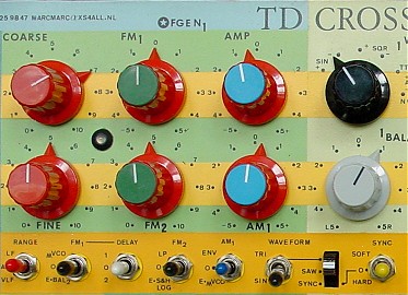
 Have a view at the simplified diagram of the two fGenerators and how they are tied to the other units and together. At first glance it all looks quiet complicated. There is no other way to represent how all features are implemented because the fGenerators simply has many and it will take some time before you get acquainted with all of its possibilities. |
11.05 |
List of Controls
A list of all controls, switches, inputs and outputs with a very short description. (x) a number in brackets means which names are valid for the 2nd fGenenerator (these numbers can be printed at the front panel). |
11.06 |
Turn Pots
|
11.07 |
Switches
|
11.08 |
Inputs
|
11.09 |
Outputs
|
11.10 |
Frequency
The fGenerators have 4 Frequency controls. COARSE and FINE to set the center frequency, and two Frequency Modulation (FM) controls with external inputs and source selection switches. With a Frequency Range switch you can set the generator to operate at a certain frequency range
|
11.11 |
Coarse & Fine
With the Coarse control pot you can set the frequency of the fGen close to the desired center point. The control covers the whole frequency range. Since the frequency of the fGen is voltage controlled the Coarse control is nothing more than setting manually a certain preset voltage . This voltage is mixed with the other voltages (Fine and FM voltages) and the sum of this mix determines the frequency of the fGen.
|
11. |
Frequency Range
With the Range switch you can select the frequency range that you like to have the fGen operate within. There are 3 ranges to select. They are named as LF, AU and VLF.
|
11.13 |
FM (Frequency Modulation)
Each fGen has two FM inputs - each with a Depth control and a source selection control. The FM inputs are essential to use the fGenerators as a VCO because they make it possible to control the frequency of the generators by any external voltage source. Without an FM input a VCO would not very useful as an analogue synthesizer module.
|
11.14 |
FM Control & Speed
Normally you interface to a VCO with a relatively slow changing Voltage change. No matter how fast you play at a keyboard, it still is relatively slow. If you can hit 20 keys per second you play fast and the VCO will be controlled by 20 voltage changes per second. A VCO - when designed for it - can deal with a much faster response than 20 changes per second. The fGenerators of the TD can respond to more than 11.000 changes per second. This opens the way to also FM modulate it with another audio frequency and this leads to many interesting effects. Because each fGenerator has two FM inputs you can combine both 'slow' FM modulation (keyboard etc.) and fast FM (by another audio frequency). |
11.15 |
FM Delay
The TD Cross Generator thanks its name to the way that the FM inputs of the 2 fGenerators are linked to each other. This Cross linking from one generator to the other and vice versa through their FM inputs can generate specific sounds but also may lock both generators to each other because they stabilize each other.
|
11.16 |
Phase Control
Each fGen has one FM input (FM1, FM3) which has the possibility to reverse the effect of the applied FM voltage. In the middle position of the depth control there is no modulation. Turning the control to the right means that you give more depth to the FM in normal phase (a positive voltage = positive and negative voltage = negative) but when you turn it from the center to the left, then the polarity change (Pos=Neg and Neg=Pos).
The Phase control is realized with using a voltage inverter between the FM source (what you get when turning to the right) and the left junction of the control (which thus stands for the inversion of the applied FM voltage. |
11.20 |
Wave Forms
Each fGenerator can generate the most common wave forms. These are Triangle, Sinusoid, Saw Tooth, Ramp, Square and Pulse.
When using the fGen as a modulation generator, then the wave form selection does not concern the harmonics anymore. Instead, the modulation effect of the selected wave form is essential (the modulation curve). For example: a sinusoid used to create vibrato sounds more natural than a triangle curve. A Saw Tooth may let the tone rise and then fall back abruptly while a Ramp does the opposite (rise abruptly and then goes down slowly). |
11.21 |
WF Switches
With the wave form switches SIN/TRI and 3 way switch SAW/SYNC you can set the wave form.
|
11.30 |
Amplitude
Each fGenerator has a two-quadrant multiplier build in. This multiplier is actually a VCA which respond both to a positive and negative control voltage. Thus increasing the control voltage negatively has the same amplitude increasing effect as when increasing the control voltage positively, but the phase of the output will be reversed. For an output within the audio range this only will be noticed only in some rare occasions but, when the fGen functions as a low frequency generator for modulation purposes the phase of the signal becomes rigorous when using a Saw Tooth wave form because reversing it will turn it into a Ramp wave form. |
11.32 |
AMP Control
With the AMP control you can set the amplitude level of the SIN/TRI wave form output (The SQR output is not affected). When the AMP control is set in its middle position, the output amplitude is zero. Turning the AMP control to the left or right will increase the output amplitude.
|
11.33 |
Practically
Reversing the phase manually by using the AMP control goes smooth. Rather than a reversing switch which would abruptly switch a Saw Tooth to a Ramp you can turn the AMP control from one side to the other to reverse and your speed of turning determines a certain flow of this reversing. This becomes valuable when the fGen is used to generate low frequencies to modulate other units. |
11.34 |
AM (Amplitude Modulation)
Of course you also can externally modulate the multiplier by using the AM input and Depth control.
|
11.35 |
AM Depth Control
As already explained, a positive versus negative control voltage influences the phase of the output wave form of the fGen. Therefore the AM control has the ability to reverse the input signal applied to the AM input. Setting the AM depth control in its middle position is equal to set a zero AM modulation depth. Turning it to the right causes the effect of the AM input to increase in phase with the AM input signal. Thus a positive AM voltage will control the multiplier also as such and a negative voltage will also remain as such. But, when turning the AM depth control to the left, the AM input signal will be a reversed control signal (pos=neg / neg=pos). |
11.36 |
AM Practically
To illustrate the possibilities of combing the setting of the AMP control and the AM control possibility to reverse its control voltage some examples: |
11.36b |
1) As a normal VCA
Setting the AMP control in its middle position will set the output amplitude to zero. An applied envelope signal to the AM input and the AM depth control turned to the right will cause the output of the fGen wave form to follow the envelope by turning the envelope voltage curve into an amplitude curve (volume curve if the wave form is connected to an amplifier). The "volume" becomes a function of the applied AM voltage curve.
|
11.36c |
2) Wave form inverting VCA
When you have set the AMP control at its middle (neutral) position, then the fGen output will be zero. When an Envelope curve comes in through the AM input and the AMP control is turned fully to the left then the positive AM signal will be inverted and becomes negative. Due to the two quadrant function of the multiplier the output signal of the fGen will now follow the AM applied voltage curve as in example 1) but now there is an important difference in the phase of the fGen output signal: the wave form now is reversed (inverted). For symmetrical wave forms such as a triangle this has no effect (normally) but a Saw Tooth now has turned into a Ramp wave form!
|
11.36d |
3) As a mirror (anti) VCA
When you turn the AM control fully to the right the output amplitude of the fGen is at maximum when the AM signal is at zero Volts. When the AM control is fully turned to the left (inverting position) and a positive AM signal comes in (envelope curve for example) then, the result is that the VCA follows this curve reversed and thus the output amplitude of the fGen becomes less when the AM applied input signal becomes higher and vice versa. Practical use:
Another use is to have the output amplitude of the fGen depend on a keyboard voltage: The higher the keyboard voltage (key more to the right) the less the amplitude of the fGen output. With this one could control (compensate) the amount of upper tones relative to the keyboard position. Either creating more upper tone when higher notes are played or vice versa. Or, when routed to an effect device add more or less the effected fGen to the total sound depending on the keyboard position. Another use is to use the mVCO modulation signal to modulate both fGenerators in a opposite VCA function and created a special timbre tremolo or modulation. |
11.36e |
4) Rare phase shifting VCA
When you do not turn the AMP control fully to the left but only a part, then the zero point of the Envelope curve is actually shifted to another point in the curve. The effect is that from a preset fGen output amplitude, the amplitude goes down for the first part of the Envelope curve, then goes up and down according the following part of the curve and then goes back to the preset amplitude again - following the last part of the curve. Thus there are two moments that the fGen output amplitude crosses zero level. Also, two times the fGen output signal reverses its phase which becomes very effect full when using low frequency signals for modulation purposes (a Saw Tooth turns into a Ramp and back again. This is really something you have to experiment with.
Practical use:
When it comes to Audio signals a phase shift of 180 degrees is only effect full in relation to a signal that can be seen as a counterpart of that signal and being in a certain state of phase differently. "TWINS out of phase" would be a good abstract description of possible imaginations of the effect. Two persons - looking from the outside the same but due to their differences in character interact 'unexpected'. From a technical point of view it can all to be predicted but the musical working out has may surprises in stock. In the audio range the Phase difference becomes interesting at the point of change (the point of phase change relative to the counterpart). In the Low and Very Low frequency range the phase change is very much noticeable. Either because the wave form is not symmetrical or the timeline experience in relation to the timeline of the phase-change is slow. |
11.40 |
Balance
Each fGenerator is equipped with an output balance control which can balance the output signal between a selected wave form from one fGen and a selected wave from form the other fGen. |
11.41 |
Wave form select
With the wave form select switch, you can select from 6 positions - each representing a wave form variation.
Each of these wave forms has is own possibilities. |
11.42 |
+SIN / - SIN
An inverted Sinusoid looks the same as a non inverted one since a sinusoid is a symmetrical wave form. This also is true for a Triangle wave form but, when you set a fGen to a Saw Tooth function, then inverting this wave form becomes effect full - it turns into a Ramp wave form.
|
11.43 |
Practically
Whatever patch you made, it is always useful to simply play with the wave form selectors to see what effect is has on the sound/control. Sometimes you will not notice any difference between changing from +SIN to -SIN but for other occasions it might be useful.
Using the SIN/TRI output of the fGen (in Phase) in combination with the wave form selected balanced output set at -SIN, gives you two outputs with the same wave form and frequency but in inverted ration. This can be useful to control two functions (parameters) in opposite directions.
Realize that the +SIN and -SIN positions not only means selecting a Sinusoid wave form but, also the Triangle and Saw Tooth and Ramp wave forms - depending on the SIN/TRI 2-pos and SAW/SYNC 3-pos switches. |
11.44 |
+SQR / -SQR
The difference between these two position is, from a phase point of view, the same as with the +SIN and -SIN positions. Everything that was said about the +SIN and -SIN positions are more or less valid for the +SQR and -SQR positions.
|
11.45 |
+TTL / N
The +TTL position is from a functional point of view the same as the +SQR position but electrically they differ. The +SQR and -SQR positions deliver a voltage between minus 5 and plus 5 Volts. The +TTL deliver a zero to plus 5 Volts signal. This has to do with the fact that usually logic controls not operate with negative voltages. All the TD inputs are protected for out ranging voltages but are other external devices too? You never can be sure, thus when you like to control external logic inputs by the fGenerators and thus you will use a SQR signal, please use the TTL output and/or wave from select unless you know for sure that you are allowed to apply negative voltages to the inputs of the external devices.
The "N" position is an inverted +TTL signal. Thus instead of jumping between zero and +5 Volts its jumps from zero to -5 Volts. You cannot use this signal for logic control but you can use it for analogue control. The effect is the opposite of the +TTL signal. In context to the above described FM control, a 2 step sequence will go down from its center position instead of going up. |
11.46 |
Balance Control
The Balance control is an important control in combination with the Wave Form select for using both fGenerators in Cross Generate mode. This is because the internal connections between the two fGenerators. Both balance outputs are in Cross Connection to both FM controls (AM can be patched). This means that the input selection of the FM input can be routed to the balancer of the other fGen by using the input select switches. This internal wiring (which can be selected/broken as wished for) is an important playful matter. It is the essence why the device is called "Cross Generator". Controlling one generator with the other is nothing special but feed backing the controlled generator back to the one that controls makes the conceptual difference. Putting both the FM input selection switches into their "E-BAL" position let both fGenerators control each other by FM trough both balance controls and their selected wave forms. |
11.46b |
Cross Feedback
You may notice that each balance control is balancing between its own selected wave from and one selected from the other. This in context to having the fGenerators into Cross Feedback control creates a complex controlling each other function. Here the motto is definitely: experiment with the wave form select, the balance control position and the way that one or both fGenerators are simultaneous controlled (FM and/or AM) by external sources too. Also, by using patch cables to inter link the balance controls to the AM inputs. Use a 'FM cross' and a single AM path from one to another fGen and route the other AM and another FM path through the Sequencer and S&H units will lead to very unexpected sounds which are hard to predict other than mentioning the idea of it in abstraction. |
11.46c |
Explore!
Let there be something to explore without the designer already at forehand knows what is possible or not. When the "FF Cross Generator" was designed in 1984, it was the idea to design a potential of letting the user to become an explorer whom could find its very own originality. Now, with the "TD Cross Generator" this concept is copied with many extra features to challenge the user to go even deeper.
Although, the balance stages in Cross Generating patch seem to be a quiet simple idea, the conceptual ground and the way it is realized go beyond existing manufactured designs. The reason that manufactures did not implement this Cross Generator idea lays probably in the fact that aiming at the creativity of the user from a commercial point of view is at least problematic. To go short: here lays an opportunity to explore possibilities for creating your very own sound by taking the energy to research my suggestions and realize that they are nothing more than suggestions in abstraction - on purpose not worked out to give space to the individual approach. |
11.47 |
Inputs
Which signal is selected for the left side of each balance is determined by the wave form selector. Through these selectors also two external inputs can be selected. These are called AUX1 and AUX2. AUX1 connects to wave form selector 1 and AUX two to the wave form selector 2.
The second Balancer has also two inputs that connected directly to the balancer itself and thus can be used completely independently (to function as a balance unit which provides a balances signal for other purposes than balancing the fGenerator outputs and FM/AM feedback.
|
11.48 |
Outputs
Both the wave form selectors and the balancers have outputs:
|
11.50 |
Sync
Each fGenerator can be synchronized with an external sync signal. Internally the sync inputs are interconnected to the SQR outputs of the other fGenerator. Thus the sync input of fGenerator 1 is interconnected with the SQR output of fGenerator 2 and vice versa. |
11.51 |
Sync Select
To have the Sync feature to become active you have to set the wave form switch into its SYNC position. Whether you set the TRI or SIN position does not matter (only some change in the amount of harmonics).
|
11.52 |
Switch Sync: Hard-off-soft
With the SYNC switch you can select between HARD SYNC or SOFT SYNC or OFF (no sync). |
11.53 |
Hard Sync
If the input sync signal is above 70 mV it pulls down the fGenerators output wave form down to its minimum voltage and keeps it that way until the sync input signal drops below 44 mV again. This can be also seen as a gate feature. When the sync signal also is an audio frequency the effect may be quit similar to a SOFT SYNC but not necessarily. This depends on the frequency difference of fGenerator settings and the sync frequency. The sync input frequency can be heard as dominant in the output wave form of the fGenerator.
|
11.54 |
Soft Sync
In contrast to the Hard sync, a Soft sync mode lets the frequency of the fGenerator to be dominant over that one of the sync input frequency. Only at an up-going edge of the sync input it will cut the wave of the fGenerator output shortly to its minimum. It actually will reset the wave form for a moment and then immediately let the fGenerator to continue with generating the wave. |
11.55 |
Practically
The result of a Soft Sync is that the originally set frequency or pattern that is currently running remains intact but the timbre colouring of the frequency is determined by the frequency of the sync signal. The effect can be somewhat similar to a filter. Playing with the sync frequency will let you hear remarkable timbre changes of the frequency of the fGenerator.
The effects of a hard sync was not often implemented in synthesizers but is worth experimenting with for rare effects. |
11.60 |
Basic Use
The basic use of the TD fGenerators is to generate audio frequencies to be heard as tones. Either varying fluently by manual control or jumping in pattern - played by keyboard or steered from the Sequencer and/or S&H module.
|
11.70 |
Extended Use
I see it as a gift to my client to provide an application that does not limit to my own experiences and dreams. Instead, I provide a tool that go beyond my own range of experiences. This does not mean that I simply mess around with the electronic design within its 'normal' purpose. Not at all! What I do is trying to have all modules that I design respond to any idea one might come up with. This only can be achieved by breaking ones head over certain prosaic problems of electronic limitations which need to be solved in both a technical an conceptual manner. The fGenerators not only can generate audio frequencies but also Low, Very Low and high frequencies. The Low spectrum suits very well for modulation purposes. Actually you might give the TD as a whole the function of generating a variety of complex modulation signals that interact with a synthesizer setup build from other analogue synthesizer or digital/MIDI ones with Voltage to MIDI interface. You then will find out that setting up a complex modulation setup with the TD is much more interesting than by digital/computer synthesizers. Although the TD is built as a stable piece of electronics, still the fact that it mostly contains analogue electronics will lead to just that little bit of natural existence which makes the difference towards its magic. Also, when designing the TD setup it was taken in account that the disadvantages of analogue technology can be turned into a great feature which is lacked by digital technology. The fGenerators deliver a very stable amplitude and very low distorted output of the generated frequency. It therefor also might be used for measurement and medical purposes (hearing test). |
11.71 |
Caution
Realize that when you generate frequencies above 8 kHz, you might not hear them so loud when attached to an amplifier headphone set but, they are very strong present. You easily can damage your loudspeakers with high frequencies attached to your amplifier since the TD give a straight forward and stable amplitude rather than a weighted frequency curve as most musical sources do (Tape, Records, CD, Radio etc.) |
11.72 |
Remarks
If you can see all the modules that the TD features in their abstraction of simply generating signals or treating signal and pulse and Voltage levels, then you patch up many applications with it. If you believe that plants and trees can talk --> simply add a sensitive sensor to your object of research - let it transfer the picked-up signal into a voltage and patch this to the TD. Your output will be scientifically correct translated into a tone, a sequence of pulses or -if you would like - a more creative piece of sound. An E.E.G. Pickup set also can deliver voltages that in combination with the TD can give a remarkable output. The reason that any other analogue synthesizer as being compiled from several base units is not so suitable for this, lays in the fact that all those mass manufactured analogue synthesizer either lack a stable technology or are designed for a musical purpose in a traditional meaning and thus focus on 'a sound'. The TD does not focus on any sound in particular when it comes to the electronics. Of course, by combining certain modules, researching and finally also adding certain options, the TD has a musical direction within its own appearance. Nevertheless all the modules on itself are highly designed for straight forward and neutral specifications and therefore can be practically seen as laboratory technology (despite the fact that the TD is not according the rules - specified in medical and/or military rules --> but this is only a choice for the sake of the delivery price and a not fundamental difference). |