|
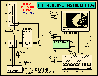
"Сторожевое" устройство Московского времени "Сторожевое" устройство контролирует тот момент, когда программное обеспечение терминала искусства "Модерн" выйдет из строя. Если это происходит, то оно переустанавливает компьютер, чтобы повторно запустить программное обеспечение.
Техническое описание "сторожевого" устройства содержится на английском языке. |
|
In general
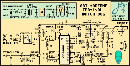
The Art Moderne terminal in Москва is an installation that continuously runs software. This software was tested for two weeks in Москва at my place of staying during the times that I was in and caused one time a crash. This was an exceptional occasion because the software was not modified for the last three years and had never had crashed in this period. I doubt very much whether it was the software that causes the crash. Maybe the computer that was sponsored to me and not new caused it or one of the heavy spikes on the 220 Volt supply. Nevertheless this one time crash make me fear to be repeated when the installation would be in the museum without anybody to check it. I thought about making a so called WatchDog which could detect a crash and then reset the computer to autoboot and restart the program again. I designed a simple circuitry and went to a shop in Москва for the electronic parts. After two hours I came out without the parts - again it was an illusion to do shopping in Москва. I decided that the one time crash would remain exceptional. ten minutes after the terminal was installed in the museum and switched on it crashed. What the f...!? because the next day I would leave Москва - not coming back for the next three months. I found a simple solution. Not elegant but effective. The Timer was programmed for a weekly programme of 6 days a week. I changed this to a daily programme for seven days a week and programmed in such a way that it would switch off every 2 hours for a minute and then restarts again. By this a crash only would put the terminal down for a maximum of two hours. (After a month the Timer started to fail :-( and happily enough now the terminal is switched on by somebody every day (who is unknown). Now, for my coming trip in May, I will take a new timer and a WatchDog circuitry that will see a crash. The diagram of this Watchdog is shown below.
|
|
How its works
For the counter chip a HEF4060 was taken (CD4060). It has an internal clock generator that runs with external timing components. R11, R12 and C12 set the clock rate at 90 milli seconds. This will generate at the Q13 output a high level each 12 minutes unless the counter received a reset from the computer. The software is modified to send out these counter reset pulses approximately every 3 seconds sequently via the MIDI output and via the Parallel output of the computer. Both these pulses are interfaced to the Watchdog to reset the counter. |
|
Inputs
The MIDI interface is build up around R3, D3 and the Opto Coupler. When the number '0' is send out via MIDI this will pull down R7 to ground for 320 µs. The parallel interface is build up around D1, C1, R1, R2 and T1. It has a Cinch input that connects to the d0 dataline of the parallel port (the NOT(busy) will be tied to ground at the parallelport plug side). When the number 1 is send out (d0 = high) and then number '0' (d0 = low again), then R7 will be pulled down for 450µs. Both ways will cause a upgoing pulse of 4ms at the MR (Master Reset) input of the 4060 (C4 will be discharged immediately but charged again via R6+R7). The function of C6, in combination with R6 is to generate a Power Up reset pulse (because it delays the the upgoing level at the MR input when the power is turned on). This is done to prevent that a random counter start would generate a computer reset when it is booting for the first time at the daily power up. |
|
Output
Q13 is connected to the darlinton T5 which drives the relay. When the computer crashed and the counter is not resetted anymore the relay will turn on for 2 seconds. However the Q13 output will stay high for 6 minutes, C25 in series with the relay will let the relay switch off again after 2 seconds. This also could be done by using a much smaller capacitor in series with the Q13 and R9 but for safety reasons it is put in series with the relay (when somehow the circuitry fails and would turn on T5 continuously or T5 would for whatever reason be in a continuous state of being turned on, then the relay still would only switch on for two seconds. R25 is add to discharge C25 after T5 has turned off again and D25 is add to discharge C25 immediately when the power is turned off. D26, across the relay, eliminates the induction pulse which is generated when the relay switches (else it could destroy T5). The relay is a M4-12H type that fits into a 16 dil IC socket and consumes only 20 mA to be turned on. The reason to use a 12V relay in combination with a CD4060 is done because the power supply range is wider with this combination and the immunity of the 4060 to external radiation is better with a 12V supply than it would be with 5V. |
|
LED indication
The relay has double throw contacts. One side is used to reset the computer by wiring the contacts parallel to the computers reset switch. The other contact pair is used to turn on the LED indication. A Tri-Colour LED is used to indicate the passive state of the relay and power supply (LED=green), to indicate the 2 seconds active state of the relay (LED=red) and to indicate the counting (LED=yellow flash). The flashing is done by using the Q3 output. C22, D22 and R21 convert the Q3 square wave into shorter pulses. R21 and C21 smooth the upgoing edge of Q3. T21 acts as a buffer and via R23 and D23 the red LED received the flash pulses. |
|
Power supply
The unit hardly uses any constant current besides the consumption of the LEDs (max 9mA). The relay draws 20mA for 2 seconds only. Nevertheless the power supply can deliver at least 80 mA constant current and a short peak current that is much higher. This is because I could not find a smaller transformer than the 1.5VA that is used now. More circuitry may be add in the future thus some current headroom is not bad. At the primary side, a S14K250 varistor protects the circuitry against on-line high voltage spikes. The fuse of 100mA slow blow against setting the whole thing on fire due to a transformer defect and the RC combination of 100N+K47 against induction spikes when the power is switched on or off. A power on/off switch is not needed because the watchdog will be switched on together with the computer and monitor by the Timer. For the transformer I used a 230V/12V/1.5VA print mouting type. Notice that the board lauout also alows a transformer with two secondary windings that are used parallel. Theory says that a 15V transformer should have been used but because not the full power of the transformer is used and the fact that the used tranformer type has a higher voltage when not fully ballasted, a 15V transformer should already would give 24V over the 1500µF capacitor. This would imply not any headroom of overvoltage at the primary side without using capacitors with a higher maximum voltage. Also the dispensation of the Voltage regulator would be higher. The 12V transformer that I used gave 21V4 DC withhout any circuitry and a 220V input. With circtuitry and LED at maximum current it gave 18V5 DC. This allows enough overhead for both a lower and a higher line input voltage (180...255V). At the secondary side of the transformer, a ceramic capacitor of 10N filters out short spikes. The diode bridge is a 40V/1500 mA small standard type. After the bridge a inductor of 330µH is put in series with the large filter capacitor of 1500 µF. This inductor will prevent very fast charging of the capacitor when power is switched on and also will filter out any high frequency spikes. The value of the capacitor does not need to be 1500 µF. A minimum value of 470 µF will do too. For the Voltage regular a 7812 is used. The 1 Amp version is used to guarantee no dispensation problems when the full 60 mA would be consumed or anything goes wrong and more current will flow. The Voltage at the input was measured at 23 Volts under operational conditions. This is quit high for a 12 Volts regulation because 18 Volts would be enough but this higher voltage is due to the fact that not all current is consumed and the transformer has a 25% higher output under no load conditions. This actually could be bad when a 240V line input would be used because this would result in a DC secondary Voltage that exceeds the 25V rating of the 1500 µF capacitor. It might be necessary to add a dummy load across the capacitor to bring down the Voltage. Another possibility is to use a 12V transformer. This would lead to 19V DC maximum but then not the fill current of the transformer could be taken (which is anyway not taken by the watchdog). |
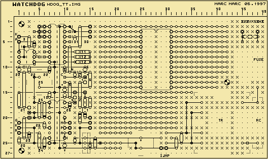
The watchdog is build on a Vero board. Below you can see the total view of the board (all components, wire bridges and path cuts). As you can see there is plenty enough space on the board left to add other circuitry. The 24 pins socket that already is lay outed is meant to be for a Basic Stamp BS2 micro controller to be add in th future.
|
|
The future Micro Controller
To the watchdog a Micro Controller will be add. The idea is to let this controller check out the whole installation (also whether it is on or not) by sensoring various parameters of the installation. The micro then could send a report by telephone to dial my mobile telephone and send a SMS message that says me what would be wrong (for example that the installation does not turn on anymore or that the monitor is defect). It would be very handy that the watchdog could bring out a report like this. It actually would be great fun too; to walk around in Амстердам an receive a message on the mobile saying that the terminal in Москва is doing OK. Of course this micro controller should have a battery backup to be able to check the state of the installation also when it is not powered. The Timer that is used now as a individual unit could be integrated in combination with the micro controller. For the moment this is all future music. |
|
Назад к Московскому указателю . . . . . Назад к основному указателю
Для ответных отзывов см. Эта страница и содержание защищены авторским правом Перевод на русский язык выполнила Кулик Ирина Александровна. irinakulik_99@yahoo.com |


