Signal Rigger Custom Design for Yntse Vughts
The Signal Rigger was designed and build in August 1987 by Marc Marc as a custom design for Yntse Vughts. The basic concept was to design a device that could transform external picked up audio signals into voltages to manipulate other sound sources. In the final design, the basic requirements were worked out to serve a wider range of transformation concepts. The device has 8 equal sets of independent electronic circuites which, for each channel, are internally patched to act as so called Envelope/Multiplier and linked to an 8 channel quadro mixer including extra filtering. The Multipliers can be tuned anywhere between a 2 and 4 quadrant function. Because each unit within each channel can be freely patched, it is possible to set up a wide range of applications. Most units not only can deal with audio signals but also with analog voltages and slow digital signals. |
The Signal Rigger is build up from the following independent modules:
|
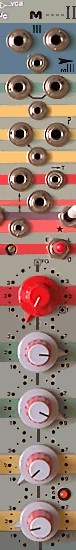
VCA/ENV This simplified diagram shows you the principle on how the 8 channels are functionally configured and interconnected. You have to multiply this diagram by 4 to understand the full extend of this part of the Signal Rigger. Master and Slave VCA/ENV channels are the same but interconnected a little different. They are called Master and Slave only for the sake of the client primary functional application. Notice that each module is independent by its own in and outputs and thus many different patches can be made to achieve all kind of functionality. |
Mixer(s) |
Monitor For the monitor configuration, there is no www diagram yet. But there is no need for this too. It works simple. With a 16-pos switch you can select between the 8 VCA outputs, 6x mixing combinations/channels, an extra mono auxiliary (V) input and the stereo auxiliary inputs. Your selection connects to a Headphones amplifier through 3 switches. These switches let you select Mono/Stereo, 'Left' or 'Right' only (mono or stereo) and a Mute switch. The headphones volume can be set with a Gain control. All together very much configured for stage / performance situations. |
Analog and still valuable The Signal Rigger was designed in 1987, using techniques (chips) from the early eighties. When the client requested at Studio STEIM in Amsterdam to create something for a project, they did not wanted to do this. The reason: the required modules to design were not considered to be innovative. They gave some suggestions for other designers and so she (the client) ended up with me.
And now, when adding some information about the Signal Rigger for the net we count 15 years later and still the concept as designed for the Signal Rigger turns out to be valuable. Even stronger: more and more people start to understand that the digital revolution did not cover all aspects of creating music or related projects. Besides the ease of a relatively small box stuffed with electronics versus one or more computers, the creative stimulance of an analog modular system is far more than with digital equivalents (besides the fact that sitting all the time behind a computer is not only boring but also bad for your health). Of course, experience and a perfectionistic attitude is a must. |
Client primary purpose - little story The primary purpose of the client with the Signal Rigger was to pickup signals from Drums - played by several drummers - and to convert this picked up signals to have control signals available to control other sound sources which then were brought together with the original sound of the drummers. At the first concert of the client in Berlin, I did assist her to overcome the cold-water-fear of the novelty. Although the concept she wanted to realize was complicated for both the technical aspects and the role of the drummers, I was very satisfied to see that the Signal Rigger was flexible enough to adapt with all kind of patches to her ideas.
|
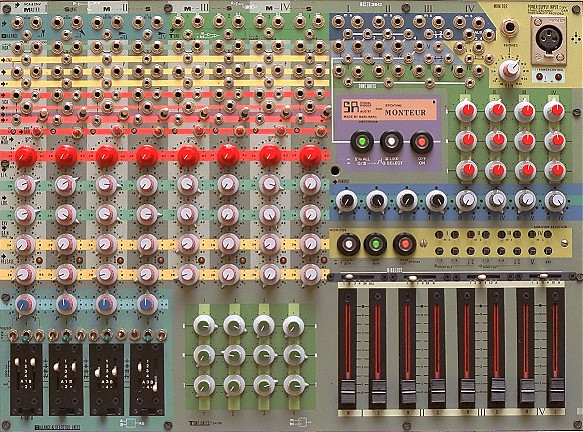
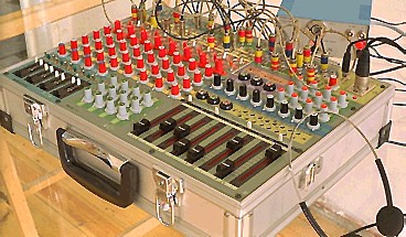
Box / Panel Design The design of the front panel is a true piece of art. It is build into a Photo-case. The front panel is even less wide than your PC computer keyboard and thus very compact (43,2 x 31,3 Cm). The power supply is external to prevent hum feed through. As you can see from the photographs, the panel is quit colorful. At the time of designing it was very special because most equipment was designed black in its overall design. The colors also indicate how in/out blocks relate to the control blocks and how the modules more or less are related. Since documentation is available on the net, many people asked how the front panels were made. From their writing I understood that people find it hard to understand how I achieved these results. Well, it is so simple: all hand made workmanship. Airbrushing, putting transfer lettering like a monk and protecting the whole with the secret of the cook (strong layer and nice matting procedure). The box is stuffed with all the electronic circuits - build up from 'prototype-like' boards. This in contrast to mass produced electronics. The advantage is that designing sensitive electronics like this requires a very well over thought board layout. Thus forces to keep the designer alert and to double think when constructing. At a second version (Montador Dos) the VCA/ENV circuits were designed for printed boards since no changes need to be made for this part of the application. Interesting is to know that the specs were not improved by having a printed board. It was only more easy to mount. The Signal Rigger is still operating without degradation (only some control parts need to have some service: pots and switches). |
Also view the GEAR catalog which contains many informative chapters on analog musical devices and fundamental issues on electronic music. For response email to This page and all contents: (C)1996 by Marc Marc Amsterdam |