26 |
Pandora Bitmap22
 |
 26.0.0 |
Bitmap22 is part of the graphic program Pandora.
This documentation about the Turtle draw function is meant as an interesting study
subject for all of you who are into making graphics & design or as being a programmer.
Back to main index
|
 26.0.1 |
Whenever you have questions about the explanation in
this manual you should refer to the paragraph number which is listed at the left side
column. This paragraph, which you are reading now for example, is numbered as paragraph
26.0.1
|
 26.0.2 |
This manual uses a stylesheet - please make sure that both stylesheet and Java option are set enable for your browser.
For response see  Marc Marc contact file Marc Marc contact file
All pages & contents are Copyrighted (C)1998 by Marc Marc Amsterdam
|
| | |
26.1 |
Pandora Bitmap22
Introduction  |
 26.1.0 |
Introduction
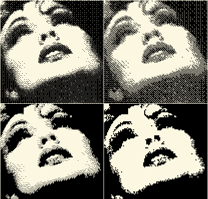  The title 'Bitmap' of this item is a little misleading because anything that can be seen on
your monitor already is a bitmap. The screen is a collection of pixels that are stored as a
bunch of Bytes - each Byte contains 8 bits. The Bitmap function creates a bitmap with
another structure - another principle. This new created format of your picture can be
manipulated in a special way to create effects that are part of what is called Image
Processing. In this case it means that groups of pixels are joined together - represented
as a numeric value - based on the combination of the pixels in the group. The collection
of these numbers represent the Image as being the Bitmap. These numbers can be manipulated
in simple ways but with a rigorous effect on the image.
|
 26.1.1 |
How it works
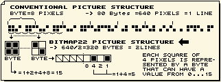  A monochrome picture is represented on your screen as a certain amount of horizontal lines.
Each line is build up from a certain amount of pixels that can be black or white. In the
memory (or File) these picture lines are stored as a stream of so called Bytes - each
containing 8 bits as being a bit for each pixel. When a pixel is black, the bit is turned
on and when it is white the bit is turned off. Each of these Bytes also can be seen as a
binary number. Thus; each possible combination within a group of 8 pixels on a line can be
represented as a number. For the Bitmap item the pixels of the picture will be reorganized
differently. Instead of a stream of Bytes that each contain 8 pixels horizontally on a row,
it is organized as a stream of numbers that each represent 4 pixels in a square. The reason
for this is the fact that with this format certain numeric manipulation can be done that
suit to the purpose of Image Processing. View the illustration below and resume these
abstracts again.
Now that you know that each 4 pixels in a square can be represented as a numeric value from
0...15 and that "0" means all four pixels are white and that "15" means that they all are
black, you have to consider the following: Imagine that you decrement each number from the
map. 15 will become 14, 14 to 13, 13 to 12 etc, a zero number will remain zero. Then this
manipulated Bitmap will be transferred to a picture again. What will be result? Each number
of 15 became now 14 and thus; the 4 bits in a square that were all black and made the
number set to a value of 15 will now not all be black anymore because the value of 14
means another pixel combination than a value of 15 and thus they cannot all four be black
anymore. Instead only three of them will be black. But, which ones? There are 4 possible
pixels in the square that could be set to white and thus 4 different combinations are
possible with having 3 pixels in a square Black. Therefore these four combinations have
there own number. Which pixel will be set to white for each of these four numbers is a
arbitrary thing - based on the fact that this concept also needed to be programmed. Take a
view at the menu and see that all possible pixel combinations are there.
|
| | |
26.2 |
Pandora Bitmap22
Menu  |
 26.2.0 |
Bitmap22 menu
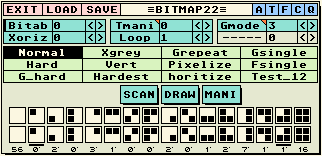
 To have a picture converted to the Bitmap structure, you first have to SCAN it. To convert
the Bitmap back to a picture you have to DRAW it again. Both these options can be found on
the menu. When you click at [SCAN], Pandora will flip to the picture screen and Scan the
picture (or Area). When you click at [DRAW], Pandora will flip again to the picture screen
to draw the Bitmap (that might be changed due to your manipulations).
|
 2.1 |
Keys
When being On Screen you can also give the Scan and Draw command with the keys:
Ctrl+[S] Scan Area into Bitmap.
Ctrl+[D] Draw Bitmap to Area.
|
 26.2.2 |
Table Display
The two rows with the 16 little squares - each with four dots, represent the Scan_table
(upper row) and the Draw_table (lower row). The Scan_table is to indicate which pixel
combination is scanned. The Draw_table is used to Draw the map again. Thus the definitions
that are displayed in the upper row will be converted to those of the lower row. When you
edit the square at the lower row below the full white square of the upper row all four dots
black and then Draw the map again, you will find out that all the full white squares from
your picture now will become fully black. As you can understand, you can change any dot at
the lower row to convert a certain pixel combination to another one and thus change the
state of art of your picture.
|
 26.2.3 |
Edit Table
To change the definition of the Draw_table (lower row), you simply click at the dots to reverse the colour.
|
 26.2.4 |
Select Table / Bitab
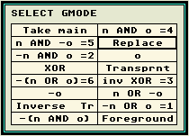
With the parameter Bitab, you can select one out the 12 presetted Bit_tables (Draw_tables). You can change them for your application.
|
 26.2.5 |
Rotate Table
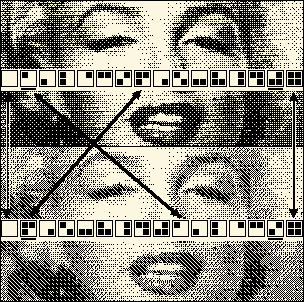  Below the Draw_table you can see two thick underlines at two different squares. These are
the rotate indicators. You can move the definitions clockwise or anti clockwise by using
the cursor keys [Left] and [right]. The rotate indicators set the limits of the area that is rotated
(the amount of definition and the start & end point).
Change Rotation indicators
To change the rotation indicators (to rotate within a different area of definitions), you simply click the indicator and then click the desired new location.
The Impact of rotating the Draw Table
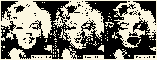
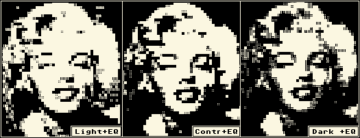
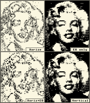
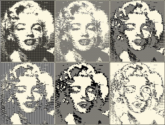
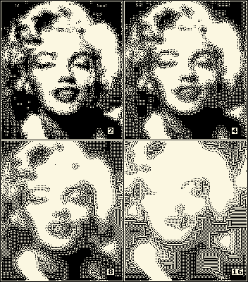
When you rotate the Draw_table and Draw the Bitmap again you will find your picture changed.
This is because each pixel definition will be linked to another combination of the Draw
table. The illustration illustrates possible the effect on a picture.
|
 26.2.6 |
Bitmap ratio indication
Below the Draw_table definitions, you can see numbers indicated. These values indicate the
percentage ratio for each definition from the Scan_table that is scanned.
 If below the
full white definition the value 56 is listed, this means that 56% of your total image
contains full white squares. This statistical information is very useful to see at which
definitions it is of any use to change the Draw_table definition (if the value displays
zero it is not much of a use to change that definition). If below the
full white definition the value 56 is listed, this means that 56% of your total image
contains full white squares. This statistical information is very useful to see at which
definitions it is of any use to change the Draw_table definition (if the value displays
zero it is not much of a use to change that definition).
When the percentage of a certain definition is less than 1%, the display will show a
zero with a little point aside. This can mean any percentage between 0.0000156% and
0.0015625% (1/64000 and 1/639). To explain these numbers (incase it matters to you),
you should know that a full screen contains 64000 squares of each 4 pixels. thus;
1%=64000/100=640 squares.
|
| | |
26.4 |
Pandora Bitmap22
Alternating Flags  |
 26.4.1 |
{F}Patternize
When the {F} flag is set the Bitmapped image to be set (Draw) will be Patternized by using
the current selected Fill.
|
 26.4.2 |
Auto loop
The other alternating flags [AT-CQ] serve the Bitmap Auto loop function. With this Auto
loop, you can let Pandora sequentially execute different settings to draw the map. They
will pass by while you can easy sitting in your chair and study the results. When you exit
the Auto Loop and return to the menu, the menu settings will set according to the settings
that were used to execute the last result. This features the possibility to 'auto scan'
for a useful parameter setting for a certain image.
|
 26.4.3 |
Speed
The parameter Speed sets the interval speed of the events in seconds.
|
 26.4.4 |
{C} Cycle presets
To set the Auto Loop function to cycle the presets, you have to set the {C} flag enable.
The cycle starts at the current selected preset and ends at the highest preset index
(the lowest one most to the right) and then begins with the current selected one again.
|
 26.4.5 |
{C+T} Cycle Draw_table
When both the {C} and the {T} flags are set, the Draw table will be cycled. the cycling
starts from the current selected table and ends at the highest Table index (11) and then
starts again with the current selected one.
|
 26.4.6 |
{C+Q} Rotate bitmap
When both the {C} and the {Q} flags are set, the current selected Draw_table will be
rotated 1 step to the right after each event. The edited rotation points will be taken
into account.
|
 26.4.7 |
{C+T+Q} Cycle table and rotate
This combination will both Cycle the Draw_table and rotate the table 1 step to the right
after each event.
|
 26.4.8 |
{F} Also scan
To Scan the result of previous event again to be used for the next event.
|
 26.4.8 |
{A} Auto fixate
After each event the result is stored as a picture and then Pandora jumps to the next
screen. When all available screens are used, the Auto loop will be exited and the original
start screen will be put back again.
|
 26.4.8 |
Hold Mode and Key controls
When you click LeftMouse or hit any key, you will enter the Hold mode. This is indicated by the
text [Hold] at the left upper corner of the screen. Being In this mode you can use the
keyboard command that are listed below:
- [Esc] Exits the Hold mode and the Auto loop.
- [O] Put back the Original picture
- Ctrl+[F] Fixate the current screen
- Ctrl+[C] Store screen to Clipboard
- [Space] Exit Hold mode
- [N] Put the Result_screen again.
- [Fkeys] Flip screen
- If you click LeftMouse, you will exit the Hold mode and return to the Auto Loop mode.
- If you click RightMouse, you will exit the Hold mode and also will exit the Auto loop mode.
|
| |
by Marc Marc (C)1991...2001
|
|


