1.0 |
m2 VCR4Custom Designed GearReverb
|
 1.01 |
Introduction
The m2VCR4 is an unique device which is composed around 4 large high quality reverb spring cabinets. The configuration with the springs is designed to get the most out of this antique electric/mechanical reverb cabinet system. Furthermore 5 other supporting modules are incorporated to be able to create a wide range of reverb effects. And if this would not be enough, it all is available twice on the m2VCR4.
For each of the spring sets, there is one which is damped to turn it into a spring with a significant shorter delay. This is done mechanically in an original way with the result that can be the best described as an old fashion cellar sound. The short and long delay can be balanced. Because the m2VCR4 is modular, you can make many alternative patches to explore your creativity and originality. Also, if you do not make any external patches, you still can change the setup by using the routing switches and the Voltage Control parameter settings.
The m2VCR4 is built into a wooden case of 34 Cm wide ("13.4), 17,5 Cm high ("6.9) and 50 Cm deep ("19.7) but can be transformed into a 19 Inch case.
The m2VCR4 served many projects and now will be completely renovated to serve a new owner. The front panel will be airbrushed in full colour to match a modern exclusive look (see to view how this can look like or have a glance at the illustration below.
The m2VCR4 also can be newly build, based on the case and In/Outs you prefer.
See pricelist
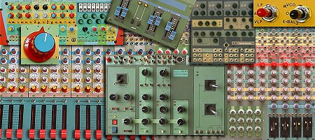
View colour variations on airbrushed panels
|
 1.02 |
Block Diagram
First, take a peek at the simplified functional block diagram. You will notice that it all looks complicated at first glance. Well, you can't have a modular analogue device with many possibilities and - at the same time - having it simple to understand in a minute. But, if you later on will read the functional description, you will learn about the m2VCR4 better. For now, just try to follow the setup more abstractly.
|
1.03 |
About Spring Reverb
Before I will explain the functionality in a practical way, I first will explain something about the Electric Mechanical Reverb system in general and how the m2VCR4 must be seen in this context.
The spring cabinet
The electrical mechanical Reverb spring principle is the first 'electronic' imitation of the natural phenomenon which is called Reverb. Before this was invented, studios did achieve the effect with special constructed cellars. The spring cabinet which is used in the electronic mechanical reverb system is an imitation of this.
The sound signal is applied to a coil through a special driver circuit. The magnetic field of this coil changes in function of the applied electrical audio signal. In the center of the coil, a spring is hanged up in such a way that it vibrates in function of the magnetic field vibrations from the coil. And thus the electrical vibrations of the applied audio signal are transferred to a mechanical vibration of the spring. It cost time for these vibrations to reach the other end of the spring. This is the delay time. The signal is at this other end of the spring then is transferred back to an electrical vibration (amplitude variation) in the same way with a coil (but now in a reversed way). The received vibrations must be amplified by a frequency corrected 'MIC' amplifier to boost them up to a LINE level.
At the same time the vibrations of this receiving side of the spring also vibrate back to the beginning of the spring again (there where it came from). Thus, the vibration keeps on going forward and backwards in the spring (mechanical feedback). But, each time the vibrations gets weaker. This weakling curve determines the reverb decay curve and time. In theory a fantastic system.
Practice Vs. Theory
In practice there are disadvantages as you probably have experienced when using a spring reverb device. To mention: large amount of harmonic distortion, limited frequency range, nonlinear frequency response, fixed delay time & decay time and mechanical sensitivity. Yet, the spring reverb became extremely popular and build in most guitar amplifiers. Then, when the electronic and digital delay lines became available the spring reverb was considered obsolete for 2 decades. But, now it�s back again because it gives a peculiar sound which is not possible to imitate by any other principle. The disadvantages simple includes a creative value and is nowadays classical and thus a need to create a certain sound. What you probably do not know is that most spring reverb systems are not optimized but rather badly designed, either due to misunderstanding by the engineer or due to commercial reasons. A pity, because most disadvantages can be eliminated partly. When this is done in a way that the 'handicaps' can be controlled, one gains the advantages of the classical 'handicapped' effect plus all the advantages of an improved system with its extra features. Besides improving the reverb system itself, there also is a lot to gain when adding some peripheral modules to modify the reverb effect in tied context to the parameters of the input signal.
Care about details
Because we see all this from perspective of custom design, which supposed to care about the 'details' in an engineering and musically way instead of a commercial, the solution for a 'perfect' spring reverb system is real. The m2VCR4 has it all. And it does not use only one spring cabinet, but 4! Three different branches are used. Two equal ones are damped to create a shorter decay time and the two others have also different characteristics. Each of the Reverb set (it�s a DUAL - remember) has a damped and a 'normal' spring cabinet - each with its own driver and receiver electronics - optimized for the electrical specifications of the spring cabinet.
By Pre filtering & Balancing between the two Spring cabinets of each set, by balancing the two sets and different patches, you can achieve a great amount of complex reverb effects. These effects not only concern the Reverb effect it self but also - and this is important - the way the Reverb signal is controlled before and after it passes the 'Reverb system' in relation to the Direct input signal (the mix of normal and reverb signal).
High heels are hard to walk at
When comparing the m2VCO4 with other spring Reverb systems, it is not to avoid to go into details. Remember that the reason behind always implies a musically target (aim). This exhausting information has a reason. Marc Marc Amsterdam like to document the ins and outs of his musical oriented design - build up by combining 'dry theory' with practical experiments and a musically aim to achieve something beyond commercial design (those things you buy in a music store) and is very proud on this.
In the next part I will try to let you consume the basic of the m2VCR4 by explaining the controls from the moment you plug in, until you extract the effect(s) from the device to have it mixed. Thus, this will be a ' front panel' approach to guide you into a practical understanding of the m2VCR4 spring reverb device.
|
1.04 |
The philosophy
As many extras a reverb device may count, it really becomes sensational when these extras can be put into a dynamically controlled setup. This means that you do not turn a bunch of knobs to only set a fixed effect. Instead, you decide using a certain patch with setting initial values with certain knobs and switches and then having the effect change within a certain range, based on your input (you�re playing characteristics). This semi-automated principle often is the base to achieve effects which we know from nature in sense of physics but cannot be imitated very well by only reproducing these rules of physics. Instead we need a more psycho-acoustic approach. This actually is a way to achieve natural results by using certain reproduction principles with keeping in mind that a recorded and then reproduced sound 1) is a simplification from an acoustic point of view - and 2) comes to us in a different psychological context than the origin.
|
1.04b |
Peripheral Modules
The 10 modules which the m2VCR4 counts besides the reverb unit(s) itself are interconnected with each other by internal patches and trough path selection switches and can be alternatively patched up differently by using patch cables.. It is impossible to describe the m2VCR4 functionality in an easy straight forward way. For each stage - from input to final output - there are all kind of possible variations to make which may involve other modules. Therefore I first will sum a short practical overview of the modules. In particular for those whom are not familiar with the common synthesizer modules since 6 of them are involved.
- VCF (Voltage Controlled Filter)
A Filter which parameters can be controlled and modulated by an external Control Voltage to achieve dynamic effects which may depend on any relation to other sound and/or voltage sources. Simple example: to modulate with a slow wave (VC-LFO) to create a sort of filter vibrato effect.
- VCA (Voltage Controlled Amplifier)
An Amplifier which amplifies its input signal based on a control voltage. When the voltage is absent (zero) no signal can be heard and when the voltage grows also the signal amplitude (amplification) grows. With this you can amplify the input signal according a certain curve which is in another way related to the origin of the input signal itself. When modulated by a slow wave (VC-LFO), you achieve the so called TREMOLO effect. When controlled by the ENV follower, you determine a certain envelop curve which might be - for example - exactly the opposite of the origin of the input signal (ANTI VCA). Meaning: no reverb signal comes through when you play without a pause or certain interval time. But, within the intervals or when you pause long enough, then the reverb signal comes up (a very effective method to imitate certain natural reverb effects in a psycho-acoustic experience).
- VC-LFO (Voltage Controlled Low Frequency Oscillator)
Generates a low frequency wave, especially for modulation purposes of other VC modules. The frequency (speed) can be controlled by a Voltage and thus the - let�s say - tremolo effect - can be modulated in a more or less complicated way and depending on other module outcomes.
- ENV (Envelope follower)
Transforms the audio signal into a Control Voltage signal. Both the Attack and Release parameters can be controlled in sense of a time-parameter (speed). With this module you can have any VC module (VC-LFO, VCF, VCA) respond dynamically to an audio signal (you�re playing or voice). An ENV module is a base for many possible effects.
- EQ (Equalizer)
This is a 'TONE' control module as you are familiar with on a hi-fi amplifier. It has a strong BASS, MIDDLE and TREBLE control to equalize the reverb signal. When you cut off the BASS completely - for example - you reverb sounds quit different. For the end result of the reverb signal on itself an important module. The EQ module is not patchable. It belongs in a fixed way to the reverb module.
|
1.05 |
Functional description
Input & VCF
When you plug into 'reverb A', your signal is automatically - by internal patch - connected to the 'reverb B' unit and both ENV followers. This input signal first is applied to the VCF, a Voltage Controlled Notch/Peak filter. With this VCF you can set a fixed filtering 'colour' to eliminate (notch) a certain small frequency band from the input spectrum or in contrast attenuate (peak) it. Both Notch and Peak modes do have a very effect full response in relation to the characteristics of the reverb springs. Since we speak about a VCF, you also can dynamically change the frequency center point by a control voltage (FM = Frequency Modulation). Two FM inputs are available. One is connected to the VC-LFO (Voltage Controlled Low Frequency Oscillator) and the other to the ENV (Envelope follower). This gives you the opportunity to have the center frequency of the VCF sweep by modulating with the VC-LFO and have the center frequency be modulated based on the amplitude curve of the input signal itself. By setting certain values with the controls for all involved parameters, already a wide range of dynamic frequency response (timbre) effects can be achieved. With the GAIN (G) control you can adapt the input level to the system level and/or overdrive to create a distorted reverb effect. A LED indicates the signal level limits / overload. (overdrive).
To resume
- Input Gain control (reverb: G)
- Overload LED indication (OL).
- VCF notch/peak manual frequency control (VCF: freq)
- FM input an depth control (VCF: I)
- FM input an depth control (VCF: II)
- Switch function: Notch / Direct / Peak
Reverb
The reverb module is built with 2 spring cabinets. One spring (S) is damped to shorten the reverb decay curve. The other spring (L) is responding as original meant to be.
The output of the VCF is connected to the Driver amplifiers of both spring cabinets trough a frequency range switch. With this switch you can select how each spring of the set of 2 should respond.
- A = Both springs (S & L) respond to the full frequency range ('ALL').
- AH = The S spring at 'ALL' - The L spring at 'HIGH'
- H = Both springs set at 'HIGH'
The spring driver coil of each spring is adopted into the driver amplifier in such way that the whole frequency range is compensated for the type of used spring to have the spring respond as linear as possible (this in contrast to many commercial designs). Nevertheless, the low frequency spectrum range may 'feel' to be very strong. At the one hand this part of many classical reverb effects but on the other hand it might be handy when the low frequency spectrum would be cut off before it passes the spring rather than equalizing the spectrum after it has pass the spring. This is why a frequency range selector is add.
When a spring is set to 'H' (High) the low frequency spectrum is cut off. It will create a reverb effect which sounds better for the middle and high frequency spectrum.
The coil driver amps also do have an extra Notch filter included with a fixed Notch center frequency to decrease the frequency band that matches the resonance frequency band of the spring. This prevents that the all-over reverb-sound is too much dominated by the reverb springs own resonance (this in contrast to many commercial designs). It makes the spring reverb sound more neutral.
Both springs of each set do have their own Preamplifier with frequency correction compensation. Both 'Short' and 'Long" sounding springs have their own outputs brought to the front panel. With the 'BAL' control you can balance between the 'S' and 'L' spring. This balanced mix then goes into the EQ module.
EQ - Equalizer
The balanced mix of the 'S' and 'L' spring is connected to a EQ module, a 3 way equalizer with BASS (B), MIDDLE (M) and TREBLE or High Cut (H) control. Their range is from -20 to +10 dB and serve the feature to furthermore filtering the reverb sound to a desired timbre. The EQ module has its own output which internally connects to one of the two VCA external inputs.
VCA (Voltage Controlled Amplifier)
The VCA is functioning as an effect generator in collaboration with the VC-LFO and ENV modules.
The VCA has two signal inputs (I and II). Both with an input control slider. The 'I' input is connected to the balanced mix of the 'S' and 'L' spring through the EQ module and the other input is internally connected to the other spring reverb unit. To both VCA input channels also may be plugged in externally. In a normal setup you finally extract your total reverb effect from the VCA output.
On the control side there are 4 slider controls:
- M = Manual amp control
To control manually the 'volume'
- E = Exponential external amplitude modulation (AM) control
To modulate the volume exponentially.
Switch select: External/ENV (A) - off - ENV reversed (A)
- LI = Linear AM control 1
To modulate the volume linear.
Switch select: VC LFO (B) - off - - ENV reversed (A)
- LII = Linear AM control 2
To modulate the volume linear.
Switch select: External / VC LFO (A) - off - - ENV reversed (B)
With these possibilities of VCA Control Voltages, you can achieve a wide range of modulated Reverb Amplitude effects. Some basic examples:
- Tremolo, Chopping and combinations & variations.
By AM modulation the VCA with the VC-LFO wave forms (Triangle and/or Square).
- Signal Input depending Tremolo etc.
The VC-LFO modulated the VCA and the frequency (speed) is modulated by the ENV follower which responds to the amplitude of the input signal.
- Signal dependent reverb mixing.
The reverb is amplified proportionally to the input signal (this shuts down the reverb decay between staccato played notes)
- ANTI signal depending reverb mixing.
The reverb signal is suppressed proportionally to the input signal (this shuts down the reverb effect during played notes and only the decay of the reverb effect will rise when stopped playing or between notes.)
- Combinations of these effects.
Generally
Because the VC-LFO, ENV and VCA module are independent modules AND you have two of each, you can patch many possible combinations to achieve a complex reverb mixing which depend on the input signal (you�re playing the instrument or voice signal).
Nothing stops you from experimenting with the modules and using all modules in combination for only reverb unit only and have the other reverb module be used 'normally'.
By experimenting and some rational thinking in tying up the modules and selecting the routing switches, you will find out that you can achieve reverb effects which cannot be achieved with even the most modern digital delay/reverb modules.
|
1.08 |
m2VCR2
The m2VCR2 is half a m2VCR4 system. It has everything which is described for the m2VCR4 but single instead of twice. Thus two spring cabinets with their drivers and preamplifiers, the EQ, VCF, VCA, VC-LFO and ENV follower.
|
1.09 |
m2 Reverb
The m2 Reverb is a reverb unit with one spring cabinet. It is designed as a high quality reverb module without peripheral modules. It as an input gain control, Frequency response switch for the spring cabinet and an output balance control to balance out the direct signal and the reverb signal. It is a plug-in module which adds a high quality spring reverb to your sound without any further concern about other settings beside the input gain, frequency response and output balance.
|
| |
|