| 3 |
Installation The Brain Wave Lab
|
 3.1 |
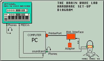
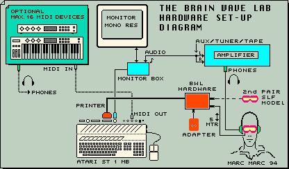
Set up diagram
To use The Brain Wave Lab, you first need to connect the hardware to your computer.
The illustration below is showing the basic possibilities when connecting to a PC.
The illustration below is showing the basic possibilities when connecting to an ATARI ST.
|
 3.2 |
Connecting the interface
The Interface must be connected to the printer port. The plug of the hardware only
will fit to one of the ports at the back of your computer. If you do have a printer switch, you
can plug in to one of the free channels.
|
3.3 |
Connecting the goggles
Plug the goggles into the interface (if not yet fixed). Some models do have 2 outputs;
plug into one of them.
|
3.4 |
Connecting the Adapter
Plug in the adapter to proper outlet (either 220V or 110V if you have an international adapter). If your adapter is not already fixed to the interface then and connect the DC wire of the adapter into the DC input of the Interface. Do not change any of the settings
of the adapter unless the Voltage change instructions which came with the hardware alow you to do so.
Your computer should have been switched on when you make these connections.
|
3.5 |
Connecting the Sound signal
PC: Connect your headphones to the speaker output of your sound card or connect the output first to an
amplifier and connect your headphones to the headphone output of the amplifier.
Atari ST: If your computer does not have its own individual sound output, you have to use a so
called 'Monitor Switch Box' to extract the sound signal from your computer. Connect the
sound output with a proper connection cable to your home amplifier. Use the Tuner, Tape or
Aux input of the amplifier and make sure that the amplifier also is switched to this input.
Connect the headphones to the amplifier and set the volume at a low level.
If you are using an external MIDI device and do not mix 'Internal sounds' with it,
you have to connect your headphones to the MIDI device.
|
3.6 |
Connecting MIDI devices
PC: When using the 'STeem package' you should check the MIDI sound settings to determine
how the MIDI data should be routed in your system. See the readme file STEEMINIT.TXT for more explanation.
When you install the STeem package the first time it might be that the prefixed settings do not match your system or your requirements.
ATARI ST: Unless you already know how to operate with The Brain Wave Lab, you should not
start testing the software by using Midi devices.
|
| | |
| 4 |
Kick Start The Brain Wave Lab |
 4.1 |
For those who want to start immediately.
PC with 'STeem Package '
- Put the plug of the hardware into the printer port.
- Plug in the headphones to the speaker output of your sound card.
- If not yet done: Unzip the package to your C:\ directory
and from the directory C:\brainlab\ the Steem.exe program. Steem will start up and
the BWL program already will be loaded into the window with 10 demo sessions loaded.
- Plug in the AC/DC adapter connection to the interface
and connect the adapter to the AC outlet. If your adapter has a power control LED,
then see immediately after plugging in whether the power control LED lit up or not.
If not: unplug immediately and check the polarity of the adapter.
- Hit F12 at your keyboard to really start the BWL program.
!Do not run any background tasks when using the BWL program (it slows down the BWL program emulation)!
- Click the right mouse key and the mouse pointer
will disappear. At the left hand bottom side The button, a small square will appear within
the execution monitor button field- indicating the execution mode.
- Check to see if the LEDs in the goggles are flashing - either Red, Green or both.
- You will hear sound coming from the headphones.
- Click the right mouse key again to stop the execution.
- If something has gone wrong, find the issue
TROUBLE SHOOTING in this manual, and after reading the information, see if you can trace the mistake.
- If this short test went well, you have to switch
on the sequencer to be able to run a full session. On top of the sequencer menu, you will find
the [VV] button. Click on it with the left mouse key.
- Put on the headphones and pick up the goggles.
- Click the right mouse key to start sequence
Nr 1. The program will execute a session of 10 Fpresets. This will cost 30 minutes.
Put on the goggles and close your eyes(!).
- The session have stopped after all of the 10
settings have been 'played'. Now, you probably will make up some conclusions. Be careful,
because what you have experienced can be irrelevant in relation to what you will experience
when you continue to work with the program.
- If you want to go onto a deeper level of the
program, you have to read the manual in order to become familiar with all of its functions.
- A hint for those who wish to run through the
other nine sequences: first press 2 on the keyboard and click the right mouse key.
The second demo now will start. After this has finished you can go on to run through the
numbers 0 to 9. If you wish to stop the sequence, then click the right mouse key.
When you like to read about these demo sessions go here.
Atari ST and PC with the 'STEEM Package'
- First make a back-up copy of the program disk.
- Put the plug of the hardware into the printer
port of your computer.
- Make sure, there will be at least 500 kilo bytes
free memory.
- Start up the program BWL_xxxx.prg
PC: Start up the emulator. The BWL program will start automatically after the emulator has
started.
- First a text will appear. After reading it,
hit any key to continue.
- The mouse points to the [LOAD] button. Click
on it. The mouse moves to the [ALL] button. Click it and a file_selector will appear.
Select J1_DEMO from the folder J1_DEMO and hit [OK]. The demo file will be loaded.
- Click the right mouse key and the mouse pointer
will disappear. At the left hand bottom side The button, a small square will appear within
the execution monitor button field- indicating the execution mode.
- Check to see if the LEDs in the goggles are
flashing.
- You will hear sound coming from the loudspeaker.
- Click the right mouse key again to stop the
execution.
- If something has gone wrong, find the issue
TROUBLE SHOOTING in this manual, and after reading the
information, see if you can trace the mistake.
- If this short test went well, you have to switch
on the sequencer to be able to run a full session. On top of the sequencer menu, you will find
the [VV] button. Click on it with the left mouse key.
- When you have not attached the headphones yet,
do it now. If you do not know how, take a view at the 'set up diagram' to check this out.
PC: connect your headphones to the speaker output of the sound card.
- Put on the headphones and pick up the goggles.
- Click the right mouse key to start sequence
Nr 1. The program will execute a session of 10 Fpresets. This will cost 30 minutes.
Put on the goggles and close your eyes(!).
- The session have stopped after all of the 10
settings have been 'played'. Now, you probably will make up some conclusions. Be careful,
because what you have experienced can be irrelevant in relation to what you will experience
when you continue to work with the program.
- If you want to go onto a deeper level of the
program, you have to read the manual in order to become familiar with all of its functions.
- A hint for those who wish to run through the
other nine sequences: first press 2 on the keyboard and click the right mouse key.
The second demo now will start. After this has finished you can go on to run through the
numbers 0 to 9. If you wish to stop the sequence, then click the right mouse key.
When you like to read about these demo sessions go here .
|
| | |
|
5 |
Trouble Shooting The Brain Wave Lab
|
 5.1 |
Stereo/Mono - Atari ST only
To have the mono sound output connected to both left and right headphones, one has to
switch the amplifier to the MONO position. If your amplifier does not have such a facility, you
have to use a converting cable. Ask your local hi-fi dealer.
|
 5.2 |
Interface connection
Printer port plug of the interface plugged into the computer correctly?
|
5. |
Monitor sound check
PC: Check Windows volume control / amplifier or MIDI device output.
ST: Check Volume-control on the monitor / amplifier or MIDI device output.
|
5.3 |
Amplifier sound
If you are directing the sound through an amplifier, check the connections.
Is the amplifier volume set open?
Have you selected the correct amplifier input?
|
5.4 |
MIDI
PC: Check the MIDI routing when you are using your sound card as a virtual MIDI device (see the readme file STEEMINIT.TXT for details).
PC and Atari ST:
If you already do have extrenal MIDI device connected, first check to see whether the
program will work via INTERNAL mode or not. If it does, switch over
again to the MIDI mode and check the MIDI connection cable to be connected from the MIDI
output of the Atari to the MIDI input of the MIDI device. Also make sure that you are using a
cable that is meant to be used for MIDI connections. Read through the manual of your MIDI
device and be sure that you can handle the instrument.
|
5.5 |
Adapter
Is the adapter plugged into the right AC outlet voltage?
Note: If you have an international adapter delivered with the set, this should be of no concern. The international adapter works in the range from 100 to 240 Volta AC.
Is the DC connection to the interface connected?
Note: If you have an international adapter delivered with the set, this should be of no concern.
Did you change the settings on the adapter? If you did, you have to run through the
manual section 'Adapter' to find out how to restore the correct settings again.
Note: If you have an international adapter delivered with the set, this should be of no concern. Make sure that the voltage position of the adapter is at least 6 volts.
|
5.6 |
Setup.
Restudy the setup diagram
Study the setup diagram again and make sure that your connections match those of it.
|
5.7 |
Get some help
You might have become blinded. See if you can find somebody who wants to run
through the whole process of connection with you step by step.
|
5.8 |
Nothing works
Incase you cannot figure out what the  is going on,
contact Marc Marc Amsterdam is going on,
contact Marc Marc Amsterdam  by Phone or Email and
explain your setup & problems. by Phone or Email and
explain your setup & problems.
E-mail: marcmarc@xs4all.nl
!!! Telephone support is only for those who ordered the hardware package from Marc Marc Amsterdam.
|
5.9 |
Position of the LEDs
To achieve an optimal light effect from the LEDs, they should be centered correctly
in front of the eyes. This can be done easily. The following test could be used:
- Set the Frequency to 0.06 Hz.
- Set the Brightness, for both sides, at 1.
- Put on the goggles and execute the Fpreset.
- If the LEDs are centered correctly, one has to see the lightened parts of the LEDs
fully when looking into a straight direction.
- If they are not centered, one can try to move the goggles a little vertically over the
face. The goggles should feel comfortable under all conditions.
- If no improvement can be done by moving the goggles, one can start moving the
Led-boards within its frame to the left or right to find its best position.
- It is possible that the shape and size of the goggles does not suit to the 'architecture'
of your face. In that case you should contact Marc Marc Amsterdam to work out a solution.
|
5.10 |
Adapter
The interface is protected against a reversed polarity at a maximum current of 1
Amp. You should not exceed the specified maximum voltage settings. These specifications came with your set.
Note: This is not relevant anymore, starting with the BWL sets from 2002 and later because the adapter has a fixed connection.
|
5.11 |
Polarity
The polarity of the adapter should be set to 'positive' (+)
Note: This is not relevant anymore, starting with the BWL sets from 2002 and later because the adapter has a fixed connection.
|
5.12 |
Voltage
The Voltage of the stabilized adapter may be set at various positions to control the maximum brightness range. See the specifications that came with your set.
Note: Starting with the BWL sets from 2002 and later, make sure that the position is at least 6 volts. Any higher position is possible to gain maximum brightness range.
|
| | |
| 9 |
General
information The Brain Wave Lab
| 9.1 |
Menu's
In contrast to a lot of other programs, The Brain Wave Lab has all of its menu's on screen at
the same time. This makes the program seem, at first glance, to be rather complicated. Once
you have familiarized yourself with the meaning of the different blocks, you will see that this
method makes it possible to work very fast with the program: it is not necessary to first choose what you are going to do before the corresponding menu appears on the screen and you also have a more complete overview on the parameters.
|
 9.2 |
Some of the menu functions are not visible. They are activated by special use of the
mouse. Details concerning these functions will be explained later in this manual.
|
9.3 |
Daredevils
Daredevils among us are free to rush through this manual. They will find out later
that they did lack some important information.
|
9.4 |
Mouse control
The program is almost completely mouse controlled and also the keyboard can be
used. All menu choices are made with the left mouse key (Lm). The right key
(the right mouse key) is used in, almost all cases, as an EXIT or CANCEL command: you exit the
menu and execute the settings or you exit from the execution back to the menu. This 'exit
principle' is also used for functions where a number of actions are required, such as copying
parameter blocks and during disk operations. !No matter where you are in the procedure,
you cancel by pressing the right mouse key!
|
9.5 |
Changing values
To change numerical values, click with the left mouse key on the [<] and [>] menu buttons
to decrement or increment the value in full steps. It is also possible to click on the number
display itself. Hold the left mouse key down a fraction longer than normal,
and a cursor appears at the display. Type a value an hit Return to have it installed.
You may also use the numerical keyboard (Enter has the same function as Return).
Notice that you always are using the input editing in the OVERWRITE mode.
| 9.6a |
- Not all adjustable values do have the [<] [>] menu buttons. In this case, values only
can be edited via the keyboard. Also, editing the floating part of values must be done via
the keyboard.
- When setting a value at zero, the minimum value that is allowed for that parameter
will be set.
- When setting a value larger than allowed, it will be replaced by the highest value that
is allowed.
- Typing 'garbage' by accident will not have 'crashy' consequences.
- Clicking the left mouse key, will exit the input editing. You also may use the right mouse
key to select another function while still in the input modus. Then, you have to hold down
the mouse key a fraction longer to enable the program to pass.
| 9.6b |
- Undo will set the original value back at the display.
- ^Clr Home will exit the input editing and generates a reset of the value to its
minimum value.
| | | |
| 10 |
Menu structure The Brain Wave Lab
|  | 10.0a |
 Desk: (most top menu bar) Desk: (most top menu bar)
My Desktop that will not generate a crash (GEM is requested to buzz off).
- Text bar: program Title & Version number.
- Disk operation menu: Load/Save with file format selection menu.
- Synchronization bar: Left/Right/Hemi: Execute mode.
- Lpreset banks: ABCD: 80 Lpresets for controlling the LEDs
- Fpreset bar: Selection of the current Fpreset in the editor.
- Lpreset parameter editor: For each Lpreset a set of Led-parameters.
- Sequencer : To run the Fpresets (up to a 100) in a sequence.
- Int & MIDI Sound menu: For each Fpreset 4 sounds can be edited (Spresets)
- Art button: To switch to the Auto-Composer.
- @S button: Switch the 'Screen saver' On/Off
- Time button: To view the clock. When clicking on it with the left mouse key, you can edit
the time.
- When the keyboard is used to input values, a cursor will appear at the display to edit
a new value.
- 'Empty' button: A squared block will appear when the execution is in progress. A
rectangular one will appear when a sequence is running.
- Kill button: Request to kill files from disk.
- Quit button: To Quit the program and return to the GEM desktop.
- Illustration menu: To display helping information.
|
10.0b |
Hence that the original menu screen is fully Black and White. For this manual the
original size of 640x400 pixels needed to shrink down to fit on the page and
is therefore put in a gray scale format. The full colors at the right hand bottom show
you how the TriColour version of the hardware would respond to the LED control
parameters.
|
10.1 |
Desk
Contents both options that can and cannot be activated on the main menu or by the
keyboard. Notice that you can enter M2desk also by pressing 2 times D and you can exit it
by pressing Esc, Undo, D or with the right mouse key (and with the left mouse key as
you are used to with GEM).
|
10.2 |
Sync-mode bar
Left/Hemi/Right determines whether the right LEDs are controlled by the left
parameter block and vice versa, or to control both left(Red color) and right(Green color) LEDs independently with the Hemi function. The choice also affects the execution of the sound parameters.
|
10.3 |
Lpreset banks
A Lpreset bank consists of 10 Lpresets on a horizontal row. There are two sections of
4 banks. Each Lpreset of a bank content the specific Led-parameters to determine the
Frequency, Pulse Width and Brightness of the LEDs. For both left and right LEDs (or color
registers) one can select a Lpreset. This selection is part of a Fpreset.
|
10.4 |
Fpreset bar F1...F10
With the Fpreset bar one selects the current executable preset. The Lpreset and
Spreset editor will show the values of the selected Fpreset. Instead of using the mouse, one
also can use the Function keys F1...10 to select the Fpreset.
|
10.5 |
Led-parameter editor
This is located below the Fpreset bar. The menu is split up into a section for the Left
LEDs and one for the Right LEDs (or color registers). For each of the 80 Lpresets of the
ABCD banks, a different set of Led-parameters can be stored. All 80 Lpresets can be saved to
disk.
|
10.6 |
Sequencer
Series of Fpresets can be run through sequentially. 100 different Fpresets can be
stored in the sequencer. These 100 Fpresets are divided into 10 divisions of 10 each.
|
10.7 |
Internal sound generator
The sound possibilities of the Atari-ST are poor in comparison to modern
synthesizers. But, in comparison to the sound of Brain-machines that are now on the
commercial market, it is a step forward.
|
10.8 |
MIDI
With a MIDI synthesizer or expander, you are able to create a Brain-machine for
which professionals are dreaming of already for years.
|
10.9 |
Sound triggering
With the sound editor, sounds can be set for each Fpreset. They will be executed in
synchronization with the flashing of the LEDs. Via the menu you have access to the
possibilities of the Atari sound chip or the standard MIDI controls. It is possible to trigger a
different sound for each of the logical states of the two LEDs.
Starting from version P4.05 you also can trigger the sounds by its own Sound Frequency Generator.
Then at each 'beat' the sound will be triggered independently from the LED frequencies.
Special is that the sounds within a Fpreset (max. 4) which are set enable are triggered sequently after each other (the cycle).
|
 10.10 |
A high tone when the left LED is on, a low tone when the right LED is on, a very low
tone when both LEDs are off and a short high Noise when both LEDs are on). When you are
using the TriColour model, the sounds are actually linked to the different colors.
| | |
| | |
 Previous part Previous part
 Next part
|
|