Sound Mover - Marc MarcDC Gates
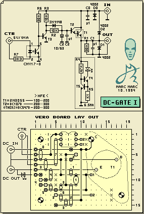
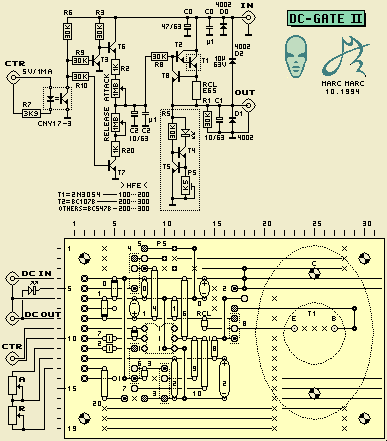
The DC-Gates have the purpose to switch the DC power supply from peripheral equipment that can be part of the total Sound Moving installation. The switching is done by the computer via the Opto Coupler input of the DC-gate. DC-Gate 1 is a minimal version. The second Gate allows to adjust a power envelope by using the Attack and Release controls. A practical application, done with Gate 1, was to switch on an auto-reverse Walkman cassette player by switching the adapter DC voltage line. Then fading in the sound, have it moved by the SM132 Sound Mover for a certain time - fade it out and then have the Walkman powered down again by the DC-Gate. Back to Sound Mover block diagram
|
|
|
The Opto Coupler CNY17-3 operates still save with this relatively low current but the CTR input wiring to the controlling unit may not be longer than a couple of meters. When controlling over a long distance is required, then the current should be chosen higher by using a lower value of R7 (K75 for 5V/5 mA for example to able long distance control). Also, notice that not the Voltage at the control input is important but the amount of current that will flow through the LED via R7. With R7 being 3K9 also 40 Volts may be applied with causing a 10 mA flow through the LED. 5 Volts however should be the minimum with R7 being 3K9. When the transistor from the Opto Coupler conducts it will pull down the base of T3 to ground. This will cause T3 to stop to conduct. The current flow through R3 will not longer go to ground. Instead it will flow trough the Base-Emitter junctions of the darlinton that is build up from T2 and the power transistor T1. The darlinton start to conduct and thus will act as a turned on DC switch between the DC input and the DC output. The switching of the DC output is done smoothly. Capacitor C2 in combination with R2 will smooth the edge of the abrupt control voltage change. Because the darlinton T2/T3 is used as an emitter follower it follows this smooth voltage curve at its emitter: the DC output. Notice that the DC output voltage always is 1.3 Volts lower than the DC input because over the switching darlinton T2/T1 two times the Base-Emitter voltage drop of 0.65 Volts is lost. (when powering a Walkman with 3 Volts, a supply of 4.5 Volts should be used - etc). When the control voltage turns to zero again, T3 immediately will conduct to ground again. C2 will discharge via R7 and the ground conducting T3. Thus, R2 will smooth the power down curve like R3 smooths the power up curve.
Protection D0 protects the circuitry against a wrong polarity applied to the DC input (which easily is done when using adapters because the polarity connection to the plug is done in two different ways - that's why mostly a polarity switch is included to the adapter). D1 protects against a wrong polarity at the DC output. Because both DC input and output use the same chassis parts it could happen that input and output are confused when wiring up the system and at the same time the adapter polarity was set wrong. D2 functions as a protection diode for T1 to prevent a reverse Voltage to damage caused by confusing DC in and output but now with correct polarity.
LED indicationTo indicate that the unit is turned on or off, a LED is used as a visual indication at the DC output. To have the brightness of the LED equal for the full Voltage range a current source is used to power the LED. R5 sets the amount of current through the LED.
Maximum ratingsWith the given component specifications it is possible to GATE a maximum Voltage of 45 Volts. The maximum current that can be delivered depends mainly on the maximum dispensation that T1 can handle. The specified 2N3054 can dispense 25Watts (with proper heat sink). This implies almost 20 Amps. 1 Amp for example would let T1 dispense 1Ax1V3=1.3Watts (1V3 is the Voltage drop across T1). |
| ||||||
|
For response see This page and all contents: (C)1996 by Marc Marc Amsterdam |

