|
Marc Marc
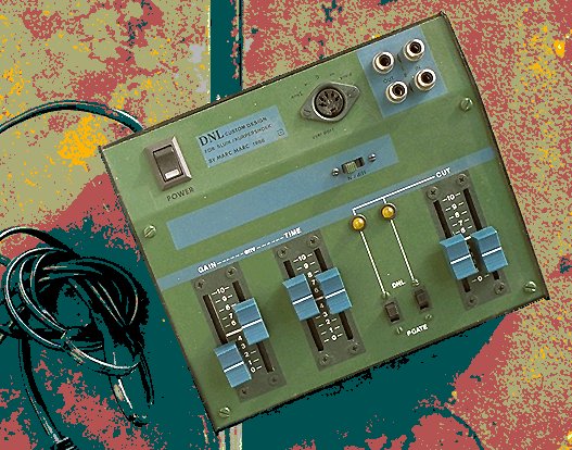
Dynamic Noise Limiter Features - In general - DNL function - GATE function - Alternating setup
|
____ DNL features:
|
|
In general This DNL device can be used very well to suppress Noise in the silent or low volume parts of Music or Voice. Any LINE input signal can be applied to be treated - to lower down the Noise in the critical low volume parts of a signal. From Psycho-Acoustic research it is know that the higher frequency spectrum may de damped in the low volume parts without harming the impression of the listener. Because most of the annoying background Noise lays in this higher frequency spectrum and becomes significant in the low volume parts or the 'silent' parts, it is very effective to have the higher frequency spectrum suppresses at these moments. When this DNL is used as a GATE, then the dynamically suppression concerns the whole frequency spectrum and thus acts as a automatic volume control which responds to the input level. This is very useful for VOICE and after a signal has passed a Hard Distortioner (guitar). It shuts down or lower downs the volume at the silent parts and lets you regulate the characteristics for this. At a certain Gain setting, it also will act as a kind of expander (low parts become lower and loud parts become louder). This Dynamic Noise Limiter & Gate is build around a so called LDR & LED combination. An 'obsolete' technology to create a Voltage Controlled variable resistant to function in a High Cut filter configuration. You find this technology in early Synthesizer design (in the VCA's) and the electronic Organs (volume pedal).
|
|
DNL function It works very simple: When there is no signal detected then the Noise suppression is at maximum and all the background Noise is suppressed (depending on the CUT controller). The higher the volume level of the signal, the less suppression of the High Frequencies (less High CUT). The response characteristics can be adjusted with the Gain and Time control. A high Gain lets the DNL faster fade into a non-suppression mode and thus only at the completely silent parts the noise will be suppressed. A low Gain will do the opposite. It then will let the DNL faster fade into Noise suppression when the volume goes down. With the Gain control you can set the response anywhere between these two extremes. To prevent that the DNL is following the input volume dynamics so fast that the suppression becomes a clearly to be heard effect and thus unwanted, you can set with the TIME control the response speed. This lets you respond the suppression to a more or less all-over characteristic. For Spoken Voice for example, you would set the TIME control at fast and for a total piece of music with many volume dynamics mixed on background instrumentals, you would tune the TIME to be respond slower. With the N/JOIN switch you can have both channels either responds completely independently (N = Normal) or combine the two detection control signals into a Joined mode to have the same effect on both channels. This means that both channels in a stereo signal setup respond more natural. |
|
Gate function When the DNL/GATE switch is set to GATE, you will let the DNL suppress the whole frequency spectrum. It is a slight modification of the electronic circuit of the DNL but, it might have rigorous effect. When used slightly, it works as a smooth expander with the result that full silently parts drop to fully to zero and thus not any Noise or whatever background signal errors come trough. Depending on the setting of the GAIN, TIME and CUT controls the output volume curve follows the input volume curve with certain characteristics.
In particular with Staccato played sounds (or instruments as Drums) the GATE function with its possible controls let you introduce certain effects related to your way of playing at the instrument. |
|
Alternating Setup Cascading You very well may patch both channel in a cascading setup (2 stages in series). Thus The output of the first stage is connected to the input of the second stage and the output of this second stage is the final output. This doubles the effect and/or combines the differently set effects of each stage.
Parallel You also could feed both channels with the same input signal and connect both outputs to your mixer to have both signal joined again. By setting a different Noise suppression or GATE curve, you can mix both these effect to be combined in a single more complex suppression / gate effect. |
|
Back to MAIN Index - Back to ELECTRONICS Index
Also view the GEAR catalog which contains many informative chapters on analog musical devices and fundamental issues on electronic music. For response email to This page and all contents: (C)1996 by Marc Marc Amsterdam |